Wednesday, March 30, 2011
I hate it when that happens
However, one of the benefits of writing to a blog is that I can readily correct errors and add new information. As an example, I've been fixing errors in the Grumman sto-wing entry off and on all this afternoon. So if you read it earlier today, you might want to look at it again...

If you have a specific request
If you have a specific request rather than a compliment, correction, or addition pertinent to the topic, it's best that you send me an email rather than submit it as a comment on one of the entries. My email address is tommythomason@sbcglobal.net.
Grumman Sto-Wing Redux
Click HERE to see a summary of Grumman's innovative wing-fold concept that it called the sto-wing.
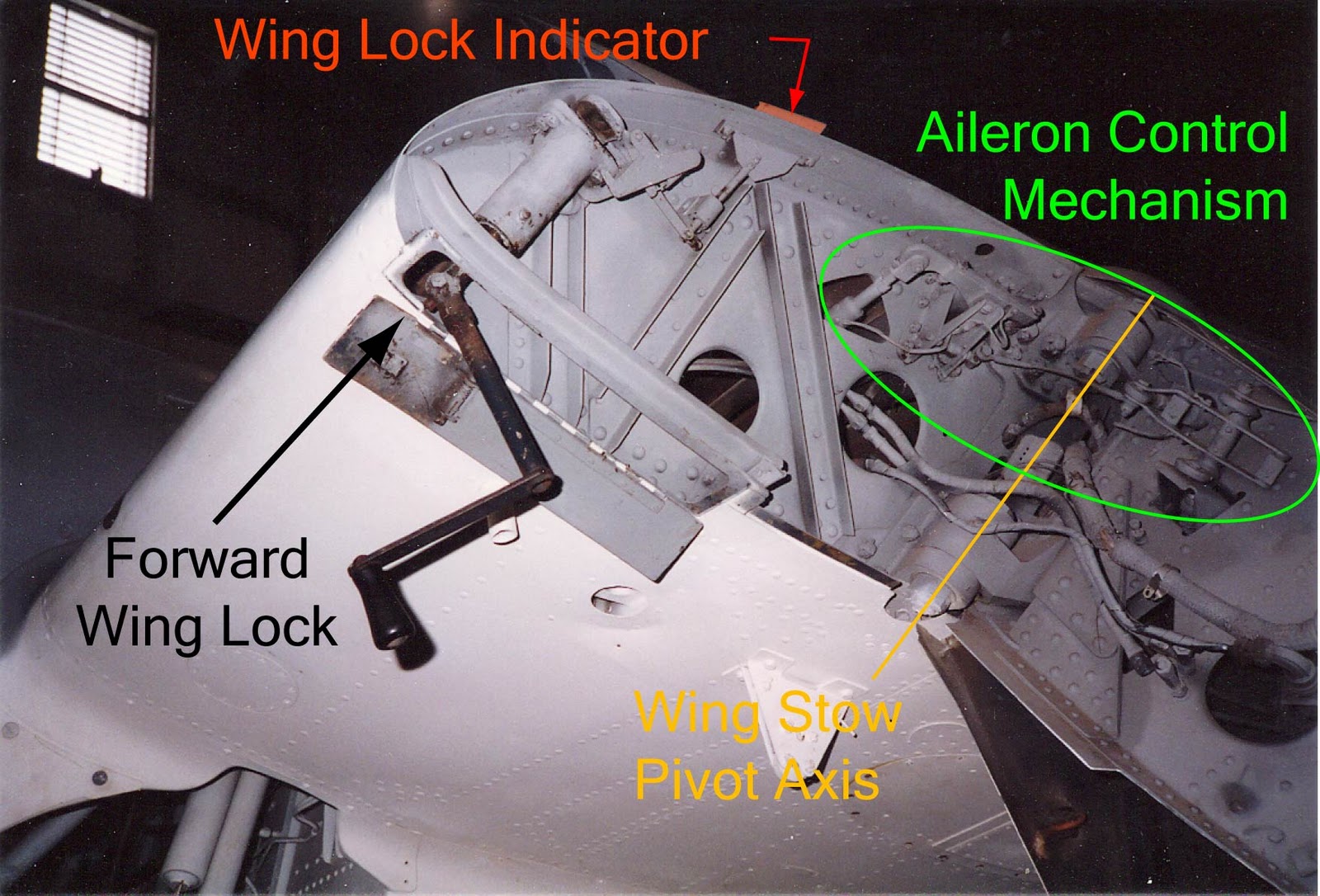
Pat Donahue wrote to ask me how the aileron control mechanism spanned the large gap created when the wing was folded alongside the fuselage. He had looked at the wing-fold area of the F6F at the National Naval Aviation Museum at Pensacola without being able to determine how it was done.
Uhh - that's a good question. As it turns out, Grumman created three different ways to do it, although the original one, on the F4F Wildcat, appears to be the only one that was used on more than one Grumman design. (Click on the images for a bigger picture.)

 In the closeup of the area encircled in green on the first picture, you'll see a rod coming out of the wing stub that pushes/pulls on a bellcrank that has two contact points on it on either side of its pivot point. If you then look at the inboard end of the outboard wing section in about the same location, you'll see another bellcrank that has an upper and lower arm connected by two small flat plates that correspond to the contact points on the bellcrank mounted on the wing stub. It's hard to see, but the left side (aft side when the wing is in the flight position) of this bellcrank is attached to a rod that disappears into the outer wing panel.
In other words, the ailerons are disconnected at the fold joint when the wings fold down and aft. When the wing is in the flight position, the two bellcranks have come together as a unit so the push/pull tube in the wing stub is pushing and pulling on the push/pull tube in the outer wing panel.
This would seem 1) difficult to rig without loss motion or overload of the bellcranks in compression and 2) to require some means of restraining the ailerons when the wings were folded. Perhaps in recognition of these drawbacks, Grumman used a different concept on each of its next two designs.
The TBF took me a while to figure out, although the mechanism is hidden in plain sight, right where Pat thought it should be, at the wing panel pivot axis.

The Grumman Archives came to my rescue with a maintenance manual. The TBF aileron control system changed from a push-pull mechanism to a cable system in vicinity of the fold joint. Two pairs of pulleys located at the pivot axis were used to transfer the motion across the fold joint This illustration depicts the pulleys on the right wing when the wings are spread:
 One pair was mounted on the outer wing panel and the other on the wing fold actuator link, with the cables crossing between the two pairs so as to not introduce any slack or tension in the cables in the folding process. All that is visible are the pulleys and cables under the link that the two wing-fold hydraulic actuators are attached to. The following illustration shows the right wing pivot axis with the wings folded, looking inboard. Note that the transition between the two sets of pulleys is on the wing pivot axis.
 For the F6F Hellcat, a link between two bellcranks was used to span the gap between wing stub and outer wing panel when the latter was folded back. The bellcrank in the wing stub and one in the outer wing panel were cleverly shaped and positioned so that when the wings were folded, the control stick imparted little or no motion to the ailerons. (Note that the outboard end of the gap-spanning link was positioned on the wing pivot axis.) Left wing folded:


The two concepts that did not break the connection between control stick and the ailerons when the wings were folded would appear to be more desirable, particularly the approach used on the F6F, but Grumman and/or the Navy thought otherwise for some reason. Grumman reverted to the original concept used on the F4F for its subsequent designs incorporating the sto-wing: the AF Guardian, WF (E-1) Tracer, and E-2 Hawkeye.
Pat Donahue wrote to ask me how the aileron control mechanism spanned the large gap created when the wing was folded alongside the fuselage. He had looked at the wing-fold area of the F6F at the National Naval Aviation Museum at Pensacola without being able to determine how it was done.
Uhh - that's a good question. As it turns out, Grumman created three different ways to do it, although the original one, on the F4F Wildcat, appears to be the only one that was used on more than one Grumman design. (Click on the images for a bigger picture.)

In other words, the ailerons are disconnected at the fold joint when the wings fold down and aft. When the wing is in the flight position, the two bellcranks have come together as a unit so the push/pull tube in the wing stub is pushing and pulling on the push/pull tube in the outer wing panel.
This would seem 1) difficult to rig without loss motion or overload of the bellcranks in compression and 2) to require some means of restraining the ailerons when the wings were folded. Perhaps in recognition of these drawbacks, Grumman used a different concept on each of its next two designs.
The TBF took me a while to figure out, although the mechanism is hidden in plain sight, right where Pat thought it should be, at the wing panel pivot axis.

The Grumman Archives came to my rescue with a maintenance manual. The TBF aileron control system changed from a push-pull mechanism to a cable system in vicinity of the fold joint. Two pairs of pulleys located at the pivot axis were used to transfer the motion across the fold joint This illustration depicts the pulleys on the right wing when the wings are spread:


Wing Spread:

The two concepts that did not break the connection between control stick and the ailerons when the wings were folded would appear to be more desirable, particularly the approach used on the F6F, but Grumman and/or the Navy thought otherwise for some reason. Grumman reverted to the original concept used on the F4F for its subsequent designs incorporating the sto-wing: the AF Guardian, WF (E-1) Tracer, and E-2 Hawkeye.
Monday, March 21, 2011
Steam Catapult Development
As part of the British development and qualification of the steam catapult, a platform containing the hardware was added on top of the flight deck of HMS Perseus.

After catapulting deadloads at dockside in mid-1951 in initial development tests, the carrier proceeded to at-sea trials in the outer Firth of Forth, beginning with deadloads and then the catapulting of six surplus, unpiloted Seafire 47s which had the wings removed at the fold joint and just enough fuel for start, warm-up, and the launch. One reportedly took umbrage at being sacrificed in even a worthy cause and managed to climb and turn back toward the ship before crashing into the sea short of the carrier. A video survives of the testing (the Seafires were not, as stated, radio controlled):
https://www.britishpathe.com/asset/51657/
Perseus was subsequently sent to the U.S. for demonstrations of the steam catapult in February 1952, first dockside at the Philadelphia Navy yard and then at sea. The steam catapult allowed the successful launch of a Douglas F3D Skyknight with a 10-knot tailwind. The existing Navy hydraulic catapult required a 30-knot headwind for the same airplane weight. The Navy immediately began planning to require steam catapults in its new aircraft carriers and retrofit existing carriers that had enough service life remaining to justify the conversion. As a result, bigger airplanes with higher performance could now be carrier-based.

After catapulting deadloads at dockside in mid-1951 in initial development tests, the carrier proceeded to at-sea trials in the outer Firth of Forth, beginning with deadloads and then the catapulting of six surplus, unpiloted Seafire 47s which had the wings removed at the fold joint and just enough fuel for start, warm-up, and the launch. One reportedly took umbrage at being sacrificed in even a worthy cause and managed to climb and turn back toward the ship before crashing into the sea short of the carrier. A video survives of the testing (the Seafires were not, as stated, radio controlled):
https://www.britishpathe.com/asset/51657/
Perseus was subsequently sent to the U.S. for demonstrations of the steam catapult in February 1952, first dockside at the Philadelphia Navy yard and then at sea. The steam catapult allowed the successful launch of a Douglas F3D Skyknight with a 10-knot tailwind. The existing Navy hydraulic catapult required a 30-knot headwind for the same airplane weight. The Navy immediately began planning to require steam catapults in its new aircraft carriers and retrofit existing carriers that had enough service life remaining to justify the conversion. As a result, bigger airplanes with higher performance could now be carrier-based.
Westinghouse: From Hero to Zero
Who would have thought that a company that didn’t even know what a jet engine was (Westinghouse) and one that had never developed a carrier-based airplane (McDonnell) could have succeeded in producing a fully operational carrier-based jet fighter on the first try during World War II? But the more experience engine and airplane manufacturers were too involved in production contracts and more conventional development programs, so the Navy gave them the assignment.
The Army got the plans for the Whittle engine, which was actually running in England, and gave them to General Electric. The Army then contracted with Bell Aircraft, an experienced airplane manufacturer, to design a land-based jet fighter using two of those engines. The resulting P-59 was, by all accounts, a dog.

Westinghouse created its engine from scratch with no outside assistance due to the secrecy imposed. It had an axial-flow compressor, which was the future, instead of the centrifugal compressor used in the Whittle engine, a dead end from the standpoint of increasing thrust significantly. The original Yankee engine, only 19 inches in diameter, worked well enough to demonstrate that the configuration was sound. One was flown under an FG-1 Corsair at NATC Patuxent River beginning in January 1944.

After development and qualification, two flight-rated versions of the Yankee powered the Navy's first jet fighter, the McDonnell XFD-1 Phantom. It became the J30.
 The Phantom incorporated all the features necessary for carrier-basing: strong landing gear, folding wings, catapult/holdback hooks, and the tail hook. It was armed with four .50 caliber machine guns. One squadron operated it briefly, including carrier qualification, but the FD lacked range, cockpit pressurization (necessary for comfortable operation at the altitudes jet airplanes operated most efficiently), and an ejection seat. This required a bigger, heavier airplane requiring a more powerful engine.
So Westinghouse scaled up the 19-inch diameter engine to 24 inches for more thrust. It was subsequently designated the J34. It powered the McDonnell F2D Banshee and the Douglas F3D Skyknight (which necessitated the change of the McDonnell designation from D to H; the original Phantom became the FH and the Banshee, F2H). And also the Vought F7U-1 Cutlass, with the addition of a government-furnished afterburner that was subsequently provided by Westinghouse.

The Navy needed still bigger, more capable jet fighters so it held a competition for an even more powerful engine. Picking Westinghouse to scale its engine up again as the J40 must have seemed like a no-brainer. Originally, the J40-WE-6 was to power the A3D Skywarrior and the J40-WE-8, which was essentially the -6 with a Westinghouse-developed afterburner added, was to provide the thrust for the Douglas F4D Skyray, the McDonnell F3H Demon, and the Grumman F10F Jaguar. See Paul Christiansen's comment below for the subsequent changes in dash number.
 For much, much more on the J40 program, see Paul Christiansen's excellent monograph:

Fair warning: it's detailed, technical, and comprehensive even by my standards, a blow-by-blow description of the engine and its development. There is relatively limited discussion of the airplanes it powered and the difficulties it caused in their development. For that however, you can read my much less detailed and technical books, Naval Air Superiority and Strike from the Sea.
Unfortunately, Westinghouse, which had been so successful up until then, failed miserably with the new engine as well as the electronic fuel control for the engine and afterburners. Development problems delayed the availability of the Navy's new fighters and long-range jet bomber, first by putting Westinghouse well being behind schedule on deliveries of engines for flight test and then by it not being able to qualify the engine for production at the necessary thrust, requiring Douglas and McDonnell to substitute other engines for the J40.
Westinghouse was not fully responsible for the Cutlass program problems. Vought was in part at fault for the cancellation of F7U-1 production because it wound up significantly overweight; however, availability of a satisfactory afterburner for the proven J34 contributed to program delays and a lack of enthusiasm for the airplane. Vought and the Navy attempted to address the weight problem with the J46 that was based on the J34 and developed concurrently with the J40. It was almost as disappointing but the F7U-3 was produced and deployed, albeit with a J46 of lower thrust and higher fuel consumption than planned, insuring that the F7U-3 Cutlass would forever be known as "gutless" and be replaced by other fighters as soon as possible.
Although production and support of the J34 continued, Westinghouse eventually exited the aircraft engine business.
Where did Westinghouse go wrong? One theory is the early successes did not result in a problem-solving culture within the engine division. Another is that the company did not continue to invest in technology and innovation like P&W and General Electric did. For example, to improve compression ratio for better thrust to weight and lower specific fuel consumption without incurring compressor stalls, P&W developed the two-spool engine and General Electric, the variable inlet guide vane concept. Westinghouse just kept scaling up the basic design, which eventually proved inadequate to the task.
The Army got the plans for the Whittle engine, which was actually running in England, and gave them to General Electric. The Army then contracted with Bell Aircraft, an experienced airplane manufacturer, to design a land-based jet fighter using two of those engines. The resulting P-59 was, by all accounts, a dog.

Westinghouse created its engine from scratch with no outside assistance due to the secrecy imposed. It had an axial-flow compressor, which was the future, instead of the centrifugal compressor used in the Whittle engine, a dead end from the standpoint of increasing thrust significantly. The original Yankee engine, only 19 inches in diameter, worked well enough to demonstrate that the configuration was sound. One was flown under an FG-1 Corsair at NATC Patuxent River beginning in January 1944.

After development and qualification, two flight-rated versions of the Yankee powered the Navy's first jet fighter, the McDonnell XFD-1 Phantom. It became the J30.

So Westinghouse scaled up the 19-inch diameter engine to 24 inches for more thrust. It was subsequently designated the J34. It powered the McDonnell F2D Banshee and the Douglas F3D Skyknight (which necessitated the change of the McDonnell designation from D to H; the original Phantom became the FH and the Banshee, F2H). And also the Vought F7U-1 Cutlass, with the addition of a government-furnished afterburner that was subsequently provided by Westinghouse.

The Navy needed still bigger, more capable jet fighters so it held a competition for an even more powerful engine. Picking Westinghouse to scale its engine up again as the J40 must have seemed like a no-brainer. Originally, the J40-WE-6 was to power the A3D Skywarrior and the J40-WE-8, which was essentially the -6 with a Westinghouse-developed afterburner added, was to provide the thrust for the Douglas F4D Skyray, the McDonnell F3H Demon, and the Grumman F10F Jaguar. See Paul Christiansen's comment below for the subsequent changes in dash number.


It's available on Amazon.
Fair warning: it's detailed, technical, and comprehensive even by my standards, a blow-by-blow description of the engine and its development. There is relatively limited discussion of the airplanes it powered and the difficulties it caused in their development. For that however, you can read my much less detailed and technical books, Naval Air Superiority and Strike from the Sea.
Unfortunately, Westinghouse, which had been so successful up until then, failed miserably with the new engine as well as the electronic fuel control for the engine and afterburners. Development problems delayed the availability of the Navy's new fighters and long-range jet bomber, first by putting Westinghouse well being behind schedule on deliveries of engines for flight test and then by it not being able to qualify the engine for production at the necessary thrust, requiring Douglas and McDonnell to substitute other engines for the J40.
Westinghouse was not fully responsible for the Cutlass program problems. Vought was in part at fault for the cancellation of F7U-1 production because it wound up significantly overweight; however, availability of a satisfactory afterburner for the proven J34 contributed to program delays and a lack of enthusiasm for the airplane. Vought and the Navy attempted to address the weight problem with the J46 that was based on the J34 and developed concurrently with the J40. It was almost as disappointing but the F7U-3 was produced and deployed, albeit with a J46 of lower thrust and higher fuel consumption than planned, insuring that the F7U-3 Cutlass would forever be known as "gutless" and be replaced by other fighters as soon as possible.
Although production and support of the J34 continued, Westinghouse eventually exited the aircraft engine business.
Where did Westinghouse go wrong? One theory is the early successes did not result in a problem-solving culture within the engine division. Another is that the company did not continue to invest in technology and innovation like P&W and General Electric did. For example, to improve compression ratio for better thrust to weight and lower specific fuel consumption without incurring compressor stalls, P&W developed the two-spool engine and General Electric, the variable inlet guide vane concept. Westinghouse just kept scaling up the basic design, which eventually proved inadequate to the task.
Sunday, February 6, 2011
Transition to Martin-Baker Ejection Seats
Early on, even before there were ejection seats in jets, the U.S. Navy established a relationship with Martin-Baker, a company located in England and dedicated to the development of the ejection seat. Two of its officers went there in 1945 to witness ejection seat testing. Although the Navy continued to rely on its airframe contractors to supply ejection seats when required, its specifications favored the Martin-Baker design philosophy of face-curtain activation of the seat.While it didn't buy Martin-Baker seats for various reasons at the time, it did purchase a trainer/test rig from M-B and required their airplane contractors to furnish seats that were fired with the M-B type face curtain (the Air Force used triggers located on the seat's arm rests).
 The man in the fedora is James Martin, later knighted as Sir James, visiting the Philadelphia Navy Yard in August 1946 where the Martin-Baker test rig had been installed.
The early ejection seats were simply bailout assists. Even after features like automatic seat separation were added, a survivable ejection had to be initiated at least 500 feet above the ground, much more if the airplane had a high sink rate. Ejection during takeoff or final approach was not an option.
Martin-Baker was dedicated to improving the seat capability and in the mid-fifties succeeded in qualifying a seat system that resulted from a survivable ejection on the runway at speeds above 100 knots. In 1956, BuAer contracted with Grumman to install the new Mk4 M-B seat in an F9F-8T for a demonstration. Flying Officer Sidney Hughes, RAF, successfully ejected from it at Patuxent River in August 1957 while on the runway at 120 kts.

This successful demonstration resulted in a Navy contract with Martin-Baker for the Mk5 seat, which was a strengthened version of the Mk 4 from a crashworthiness standpoint. (An actuator loop was also added at the front of the seat pan to expedite ejection if required, such as an emergency during catapult launch, or when g-levels made reaching the face-curtain loops difficult.) Most in-service Navy fighters with ejection seats were changed over to the new seat, either in production or as a retrofit. It took a few years because each installation had to be developed and certified by Martin-Baker. The seats were somewhat tailored to each aircraft type and therefore identified by a prefix letter, e.g. H5 for the F4H, F5 for the F8U, and P5 for the F4D (shown here).

The changeover appears to have begun with the single and two-seat F9F Cougars in the training command. The first F9F-8T ejection on Martin-Baker seats was in September 1958. The first Cougar ejection was in November.
Martin-Baker seats were installed in F3H BuNos 146709-146740 at the factory. The first ejections using a Martin-Baker seat from the F3H reportedly occurred in March 1958 with the last in a McDonnell seat in November 1960.
The F-4 Phantom first flew with a McDonnell seat but it was quickly supplanted by the M-B Mk 5 seat in production, probably in 1960 with the second block of production airplanes. (For more detail on the change to Martin-Baker seats in general and the F4H in particular, see http://phantomphacts.blogspot.fr/2013/10/f4h-phantom-ii-ejection-seat-history.html.)
Vought was reluctant to admit that the M-B seat was better than its own (although they did install a M-B seat in the third F8U-3 which flew in late 1958). Its seat was a modification of the Douglas Escapac seat which also provided survivable ejection on takeoff and approach. However resistance was futile. M-B Mk-F5s were installed in F8U-2s toward the end of their production run and retrofitted to surviving F8Us. (Contrary to some reports, a cockpit console width change was not required, only different rails and catapult fittings plus stiffening of the bulkhead; M-B assembled the F5 with a narrower seat pan.)
LTjg John T. Kryway cut it a bit fine with the M-B seat but survived after his hard landing on FDR in October 1961 necessitated jettisoning his F8U-1:


The North American FJ-4s appear to have begun to be switched over in early 1961 at the first or second major overhaul after late 1960. The first reported ejection using the Martin-Baker seat was in September 1961. If you don't have a photo of the specific aircraft being modeled, the best bet is the original seat. The earliest example that I found of a MB seat in the FJ-4 is VA-144's 3rd deployment, November 1961 to May 1962. However, there is a picture of a reserve FJ-4B dated July 1963 with the original seat.
No M-B seats appear to have been installed in F4Ds during production at Douglas, but most survivors were eventually converted to the Mk-P5 during an overhaul.
One notable exception to the changeout to M-Bs was the F11F Tiger. A quantity of 201 seats was procured for the Tigers but they were not installed, with the exception of two F11Fs subsequently pulled out of long-term storage for an in-flight thrust reverser program.
Martin-Baker demonstrated its zero-zero seat in 1961, with the Navy procuring it in 1965 as the Mk7. The performance increase was accomplished by the addition of a rocket.
The Mk5 and Mk7 seats are easily differentiated by the parachute housing. On the Mk5, the
parachute was enclosed in a horseshoe-shaped fabric casing that was housed in a black-painted metal shell on the upper seat back. On the Mk7, the parachute was enclosed in a green composite horseshoe-shaped shell mounted on the upper seat back.

There were however, many detail differences in the headrests, ejection-initiation handles, seat cushions, straps, among the seats installed in different aircraft, services, and countries. For example, the Martin-Baker seat in a U.S. Navy F-4 was not identical to the one in a U.S. Air Force F-4. The one in the British Phantoms (the right one in the illustration above) was a third configuration.
The changeover to the Mk 7 seat in U.S. Navy fighters began in late 1967 or early 1968 with Mk 5 seats being modified to the Mk 7 configuration. The first F-4Js were produced with Mk 5 seats (deliveries with Mk7s reportedly began in December 1967) and then retrofitted, as were F-4Bs; the changeover was reportedly complete by 1970. (The last RF-4Bs were reportedly delivered with the Mk 7.) The F-8J conversions from F-8Es included the installation of the F7 seat. The Hs (rebuilt F-8Ds) after mid 1968, and all Ks (rebuilt F-8Cs) and Ls (rebuilt F-8Bs) models were also delivered with the F7 seat.

The early ejection seats were simply bailout assists. Even after features like automatic seat separation were added, a survivable ejection had to be initiated at least 500 feet above the ground, much more if the airplane had a high sink rate. Ejection during takeoff or final approach was not an option.
Martin-Baker was dedicated to improving the seat capability and in the mid-fifties succeeded in qualifying a seat system that resulted from a survivable ejection on the runway at speeds above 100 knots. In 1956, BuAer contracted with Grumman to install the new Mk4 M-B seat in an F9F-8T for a demonstration. Flying Officer Sidney Hughes, RAF, successfully ejected from it at Patuxent River in August 1957 while on the runway at 120 kts.

This successful demonstration resulted in a Navy contract with Martin-Baker for the Mk5 seat, which was a strengthened version of the Mk 4 from a crashworthiness standpoint. (An actuator loop was also added at the front of the seat pan to expedite ejection if required, such as an emergency during catapult launch, or when g-levels made reaching the face-curtain loops difficult.) Most in-service Navy fighters with ejection seats were changed over to the new seat, either in production or as a retrofit. It took a few years because each installation had to be developed and certified by Martin-Baker. The seats were somewhat tailored to each aircraft type and therefore identified by a prefix letter, e.g. H5 for the F4H, F5 for the F8U, and P5 for the F4D (shown here).

The changeover appears to have begun with the single and two-seat F9F Cougars in the training command. The first F9F-8T ejection on Martin-Baker seats was in September 1958. The first Cougar ejection was in November.
Martin-Baker seats were installed in F3H BuNos 146709-146740 at the factory. The first ejections using a Martin-Baker seat from the F3H reportedly occurred in March 1958 with the last in a McDonnell seat in November 1960.
The F-4 Phantom first flew with a McDonnell seat but it was quickly supplanted by the M-B Mk 5 seat in production, probably in 1960 with the second block of production airplanes. (For more detail on the change to Martin-Baker seats in general and the F4H in particular, see http://phantomphacts.blogspot.fr/2013/10/f4h-phantom-ii-ejection-seat-history.html.)
Vought was reluctant to admit that the M-B seat was better than its own (although they did install a M-B seat in the third F8U-3 which flew in late 1958). Its seat was a modification of the Douglas Escapac seat which also provided survivable ejection on takeoff and approach. However resistance was futile. M-B Mk-F5s were installed in F8U-2s toward the end of their production run and retrofitted to surviving F8Us. (Contrary to some reports, a cockpit console width change was not required, only different rails and catapult fittings plus stiffening of the bulkhead; M-B assembled the F5 with a narrower seat pan.)
LTjg John T. Kryway cut it a bit fine with the M-B seat but survived after his hard landing on FDR in October 1961 necessitated jettisoning his F8U-1:


The North American FJ-4s appear to have begun to be switched over in early 1961 at the first or second major overhaul after late 1960. The first reported ejection using the Martin-Baker seat was in September 1961. If you don't have a photo of the specific aircraft being modeled, the best bet is the original seat. The earliest example that I found of a MB seat in the FJ-4 is VA-144's 3rd deployment, November 1961 to May 1962. However, there is a picture of a reserve FJ-4B dated July 1963 with the original seat.
No M-B seats appear to have been installed in F4Ds during production at Douglas, but most survivors were eventually converted to the Mk-P5 during an overhaul.
One notable exception to the changeout to M-Bs was the F11F Tiger. A quantity of 201 seats was procured for the Tigers but they were not installed, with the exception of two F11Fs subsequently pulled out of long-term storage for an in-flight thrust reverser program.
Martin-Baker demonstrated its zero-zero seat in 1961, with the Navy procuring it in 1965 as the Mk7. The performance increase was accomplished by the addition of a rocket.
The Mk5 and Mk7 seats are easily differentiated by the parachute housing. On the Mk5, the
parachute was enclosed in a horseshoe-shaped fabric casing that was housed in a black-painted metal shell on the upper seat back. On the Mk7, the parachute was enclosed in a green composite horseshoe-shaped shell mounted on the upper seat back.

There were however, many detail differences in the headrests, ejection-initiation handles, seat cushions, straps, among the seats installed in different aircraft, services, and countries. For example, the Martin-Baker seat in a U.S. Navy F-4 was not identical to the one in a U.S. Air Force F-4. The one in the British Phantoms (the right one in the illustration above) was a third configuration.
The changeover to the Mk 7 seat in U.S. Navy fighters began in late 1967 or early 1968 with Mk 5 seats being modified to the Mk 7 configuration. The first F-4Js were produced with Mk 5 seats (deliveries with Mk7s reportedly began in December 1967) and then retrofitted, as were F-4Bs; the changeover was reportedly complete by 1970. (The last RF-4Bs were reportedly delivered with the Mk 7.) The F-8J conversions from F-8Es included the installation of the F7 seat. The Hs (rebuilt F-8Ds) after mid 1968, and all Ks (rebuilt F-8Cs) and Ls (rebuilt F-8Bs) models were also delivered with the F7 seat.
Friday, February 4, 2011
The Conception of the F8F Bearcat
The interweb would have you believe that the F8F Bearcat resulted from a Grumman evaluation of the Focke-Wulf Fw 190 accomplished in early 1943, possibly even at Grumman's facility at Bethpage on Long Island, New York.

There is a report of a captured FW 190 arriving at Wright Field, Ohio in August 1943. However, it seems very unlikely that it would have passed through Bethpage first for an evaluation by a Navy contractor, although I'm sure that it would have been a closely held secret if it did.
As best I can determine, the F8F originated with a memo from Roy Grumman to Chief Engineer Bill Schwendler dated 28 July 1943 requesting a predesign of a small fighter built around the most powerful R-2800 engine available and providing some additional guidelines. It was reportedly the result of previous discussions between those two dating back to at least late 1942.
A predesign drawing by Dick Hutto dated 20 August 1943 indicates that the basic size and shape, including a bubble canopy, of the Grumman G-58 were well established by then.

The story that seems more credible (and supported by contemporaneous documentation) is that Grumman's Bob Hall and Bud Gilles went to England in September 1943 to fly a captured Fw 190. I haven't seen Hall's report, but they were undoubtedly impressed by its speed and maneuverability. It seems likely that they would have returned to Bethpage with the intent to match, if not exceed, its performance and handling qualities with the new Grumman fighter that they had already envisaged.
It therefore seems almost certain that the basic philosophy that shaped the F8F was not the September FW 190 flight evaluation but the result of 1942 combat experience in the Pacific vis-a-vis the Mitsubishi Zero, the need for what amounted to a fast-climbing interceptor, and the requirement for a fighter the size of a Wildcat to operate from the small decks of the newly created escort carriers.
The Navy ordered prototypes of the G-58 in November 1943 and designated it the F8F. The first one flew only nine months later, in August 1944. Deliveries of the first production aircraft were made in February 1945.
However, the first air group equipped with F8Fs arrived in the Pacific just days too late to participate in the war. (In fact, it was first Navy carrier-based aircraft initiated after Pearl Harbor to get that far; most were canceled before reaching fleet squadrons.) Within a few years, it was supplanted by jet fighters and relegated to a training role.


There is a report of a captured FW 190 arriving at Wright Field, Ohio in August 1943. However, it seems very unlikely that it would have passed through Bethpage first for an evaluation by a Navy contractor, although I'm sure that it would have been a closely held secret if it did.
As best I can determine, the F8F originated with a memo from Roy Grumman to Chief Engineer Bill Schwendler dated 28 July 1943 requesting a predesign of a small fighter built around the most powerful R-2800 engine available and providing some additional guidelines. It was reportedly the result of previous discussions between those two dating back to at least late 1942.
A predesign drawing by Dick Hutto dated 20 August 1943 indicates that the basic size and shape, including a bubble canopy, of the Grumman G-58 were well established by then.

The story that seems more credible (and supported by contemporaneous documentation) is that Grumman's Bob Hall and Bud Gilles went to England in September 1943 to fly a captured Fw 190. I haven't seen Hall's report, but they were undoubtedly impressed by its speed and maneuverability. It seems likely that they would have returned to Bethpage with the intent to match, if not exceed, its performance and handling qualities with the new Grumman fighter that they had already envisaged.
It therefore seems almost certain that the basic philosophy that shaped the F8F was not the September FW 190 flight evaluation but the result of 1942 combat experience in the Pacific vis-a-vis the Mitsubishi Zero, the need for what amounted to a fast-climbing interceptor, and the requirement for a fighter the size of a Wildcat to operate from the small decks of the newly created escort carriers.
The Navy ordered prototypes of the G-58 in November 1943 and designated it the F8F. The first one flew only nine months later, in August 1944. Deliveries of the first production aircraft were made in February 1945.
However, the first air group equipped with F8Fs arrived in the Pacific just days too late to participate in the war. (In fact, it was first Navy carrier-based aircraft initiated after Pearl Harbor to get that far; most were canceled before reaching fleet squadrons.) Within a few years, it was supplanted by jet fighters and relegated to a training role.

Subscribe to:
Posts (Atom)

