By Tommy H. Thomason

Sunday, December 20, 2009

It Seemed Like a Good Idea at the Time VII

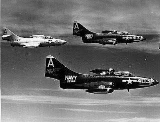
By the beginning of World War II, the US Navy had transitioned from a silver fuselage/yellow wing paint scheme with complex and colorful carrier and squadron markings to a drab medium gray over light gray one with minimal markings. During the course of the war, the paint scheme became more complex, incorporating additional colors and counter shading but still with minimal markings from a squadron standpoint. However, by the time the war ended, its airplanes were generally painted overall sea blue with various marking schemes to denote the air group to which they were assigned.

By 1950, the Navy had determined that overall dark sea blue was too visible under certain conditions for some missions, so it was inclined to adopt a paint scheme that was less so. One under consideration was the Air Force practice of leaving the aircraft unpainted, except for markings and skin panels that were not as corrosion-resistant as those formed from Alclad aluminum. Not painting aircraft had the additional benefit of reducing weight as well as initial and operating cost. Ever cautious, however, and in consideration of the much more corrosive environment that its carrier-based aircraft were subjected to, the Navy embarked on an evaluation program. Beginning in April 1952, the experiment was to involve approximately 100 F9F-5s (including F9F-5Ps and at least one F9F-2), all F7U-3s, 100 F2H-3s (and apparently some F2H-4s) and all FJ-2s. In cases where the external skins were not Alclad, they were painted with an aluminized lacquer that closely resembled the natural metal.

The natural metal F9F-5s and F2Hs were scattered among squadrons that also operated over-all blue airplanes.


The light gray areas on the F7U's aft canopy, lower side of the nose, and rudders are magnesium or other material which required painting for corrosion protection or to match the overall natural metal finish.

Some strangely colored F9F-5s resulted from aft fuselage substitutions to maximize the number of airplanes available for missions.


Although there are reports that a clear coating was used to protect the bare aluminum, it would appear from at least one report that the only protection suggested was a wax that was not readily available. By mid 1953, the results were already becoming apparent: corrosion ranging from slight to severe. Any cost benefit of not painting the aircraft was more than offset by the additional corrosion control effort required. One deployed squadron reported corrosion spots that varied up to 1/8" in diameter and several thousandths of an inch deep. In February 1955, the Navy decided to paint all its tactical airplanes in a gray/white scheme with the experimental airplanes to be painted by July 1955.

For more background on this experiment, see this 1953 issue of Naval Aviation News, pages 13-15.
Saturday, December 12, 2009

It Seemed Like a Good Idea at the Time VI

Boundary Layer Control increases the lift of the wing at low air speeds. Air drawn from the jet engine compressor is blown over the wing flaps, increasing the angle of attack at which the air flow separates from the upper surface of the flaps and the lift begins to decrease with increasing angle of attack rather than continuing to increase. In other words, postponing the wing stall to a lower speed/higher angle of attack than with unblown flaps.

This was of particular interest to the U.S. Navy because of the need to minimize the approach speed of carrier-based jet airplanes.  In 1951 a Navy engineer suggested using the problem as part of the solution, with the jet engine compressor being a convenient source of the air required.A test program resulted a few years later with a modified F9F Panther. At-sea carrier trials in 1954 demonstrated a significant reduction in approach speed, 10 to 15 knots depending on weight, which was limited by inadequate roll control at the lower speed rather than stall.

As a result, BLC was incorporated on a few US Navy airplanes in the late 1950s, although its first usage may have been in the Lockheed F-104 Starfighter which first flew in 1954. Like most gadgets, it was a mixed blessing. In at least two cases, the F4H Phantom and the F-8 Crusader (French and F-8J), it was an addition to an existing design to accommodate a necessary increase in gross weight. It might have been in the A3J Vigilante design from the beginning because the Navy wanted to be able to launch its long-range nuclear strike aircraft with no wind-over-deck at all. It also appears to have been in the F8U-3 from the beginning, Vought engineering having a penchant for incorporating this sort of thing, and the Blackburn Buccaneer. Note that all these were carrier-based airplanes, for which low-speed lift was far more important than land-based counterparts. However, as noted above, the F-104 incorporated BLC to compensate for its tiny wing and TSR2 did as well, because of its need for a high wing loading for high-speed low-level flight combined with a reasonable takeoff and landing distance.

This is a photo of the French F-8 flap system ducting taken and annotated by Tom Weinel:


Although it provided more lift at a given speed or the same lift at a lower speed as a non-blown wing, BLC was a maintenance burden, increased weight and complexity/cost, and robbed the engine of thrust on a wave off and takeoff. Troublesome failure modes included the fire hazard of a leak of the hot air in the ducting and a roll control problem on takeoff or landing if one side or the other failed to provide air for some reason. My guess is the overall experience in the 1960s resulted in BLC being infrequently taken out of the designer's tool box thereafter. The only current application that I can think of offhand is the Japanese ShinMaywa seaplane, which needs to take off and land at extremely low speeds in order to land in relatively high sea states in open water for at-sea rescue. In this case, the BLC air is taken from a compressor driven by a fifth and small turboshaft engine.

Thursday, December 10, 2009

The Reason for Those Lines on the Vertical Fin

I thought I'd mentioned this before in this blog but apparently I hadn't, because I can't find it. Back before the pilot and the Landing Signal Officer (LSO) were provided with indicator lights to insure that the airplane was at the correct angle of attack on approach, the left side of the vertical fin on most carrier-based airplanes* was marked with precisely positioned stripes. By noting which ones he could see with respect to a fixed point on the airplane, like the wing leading edge, the LSO could determine the airplane's angle of attack and signal the pilot to speed up or slow down if required.  These stripes were somewhat exaggerated on the mockup of the Douglas F4D Skyray and I'm not sure that the top one is properly located, but they illustrate the concept.

A closeup shows that the lines were marked in degrees.

The more subtle angle of attack markings used operationally are just evident on the leading edge of the fin of this F9F Panther.

These markings weren't of use at night, of course. In that case, the LSO relied on an "approach light" in the leading edge of the left wing. There were three colored lenses in front of the light so that he saw green for too slow, red for fast, and amber for on-speed based on the attitude of the aircraft at the proper approach altitude. The light only came on when the hook was lowered so it provided a positive indication that the hook was down at night. (A field carrier-landing switch was provided for practice night approaches ashore.) LSOs also used the relative orientation of the running lights (and on propeller-driven airplanes, the flames from the exhaust stacks) to determine the speed (actually angle of attack) of the approaching airplane.

Within a few years after angle-of-attack measurement and cockpit display were added to Navy carrier-based jets in the early 1950s, the LSO was provided with an angle-of-attack indication via three lights. Again slow (actually, too high an angle of attack) was green, on-speed was yellow, and too fast was red. The lights were generally located in a box mounted on the nose landing gear as shown here.

*I don't know why, but F2H-2 Banshees didn't have these stripes even before angle of attack indication became available. On the FJ-1 and F2H-1, they were placed on the nose - on both sides of the FJ-1, probably because North American didn't know what they were for...


Sunday, November 29, 2009

Air Groups and Markings in Transition

According to the caption on this National Archives picture of a VC-4 F2H-4 Banshee refueling from a VC-5 AJ-2 Savage, it was taken on 28 January 1955. These aircraft were deployed with Air Group Eight aboard Lake Champlain between 28 September 1954 and 22 April 1955.
At the time, the standard Navy color scheme was an over-all sea blue; it was about to be changed to a light gull gray over white scheme to reduce visual detection at high altitudes. The Banshee sports an experimental natural metal approach authorized in 1952, which was being tested because it saved weight and the cost of paint and painting the aircraft. It proved to not be cost effective because of the increased corrosion control and remediation effort required.

The composition of the air group was also in transition. Up until the mid-1950s, the air groups were assigned two or three day-fighter squadrons and two or three day-attack squadrons. Each squadron was marked with the air group's assigned tail code, in this case "E". Upon deployment, the air group was augmented with detachments from big "composite" squadrons, which provided the aircraft and training for special missions like night attack, night fighter, heavy attack, nuclear weapons delivery, photo reconaissance, and airborne early warning. Each of these squadrons was assigned a two-letter tail code and up until now, retained them during the deployment. For example, the VC-5 Savage is marked the "NB" of VC-5, not the "E" of Air Group Eight. Air Group Eight had also deployed with AD-4Ws from VC-12 (NE), F2H-2Ps from VC-62 (PL), and HUPs from a helicopter utility squadron, HU-2 (UR). The VC-4 Banshees were assigned the air group for all-weather fighter missions and visual delivery of the Mk 8 nuclear bomb (the big pylon that mounted the bomb is visible just outboard of the engine inlet).

In this case, the VC-4 Banshee is now marked with the air group's tail code, E, although on the original print it's clear that "NA", the VC-4 tail code, is on the tip of the vertical fin. It's also marked with a 6xx series number, which is again an extension of standard air group markings, 1xx denoting the first fighter squadron, etc. This picture is therefore an example of the beginning of the fuller integration of the squadrons with the air group that was being accomplished. All-weather fighter and heavy attack squadrons were to become assigned to the air group rather than being detachments from a parent specialty squadron. (With the introduction of the A-6, all-weather attack also ceased to be a detachment.) All detachment aircraft from the remaining specialty squadrons like airborne early warning (VAW instead of VC after June 1956) and photographic reconnaissance (VFP after June 1956) were eventually to be marked with the air group tail code and three-digit numbers on the nose in accordance with a standard scheme for the duration of a deployment.

Friday, November 27, 2009

A-12, The Gift That Keeps On Giving II

A gift to lawyers, in this case.

Back in June, I wrote: "I was surprised when writing the chapter on the A-12 Avenger II program in Strike from the Sea to discover that its termination was still in dispute. Given that it had occurred in January 1991, almost two decades before, that seemed unlikely until I discovered that it involved a $2.3 billion claim by the Navy against GD and Boeing (which now owns McDonnell Douglas, GD's original partner in the ill-fated program). That sum consisted of a demand for the repayment of $1.3 billion in progress payments and $1 billion (and apparently still counting) in interest. Avoidance of the payment of that kind of money justifies the efforts of legions of lawyers.

There were eventually two trials. The contractors won the first in 1995, which the government successfully appealed, and the government won the second in 2001, which the contractors successfully appealed. (A 2002 settlement floundered because the contractors and the government couldn't agree on the value of the "in-kind payments", i.e. goods and services as opposed to cash, to be made by the contractors.) According to today's Wall Street Journal, the U.S. Court of Appeals for the Federal Circuit has finally ruled on the 2007 Claims Court ruling against the contractors, upholding it.

It's probably finally over but I wouldn't bet on it."

And a good thing that I didn't, assuming I could find anyone who would bet against. Here's the latest, from a General Dynamics press release dated 24 November 2009:

The U.S. Court of Appeals for the Federal Circuit today denied a request for a rehearing of the Federal Circuit's prior decision sustaining the government's default termination of the A-12 aircraft contract to which General Dynamics and The Boeing Company were parties with the Navy. General Dynamics disagrees with this most recent decision and continues to believe that the government's default termination was not justified. The company also believes that the ruling provides significant grounds for appeal, and intends to petition the U.S. Supreme Court for review.

Boeing's release was a bit longer:

J. Michael Luttig, Boeing executive vice president and general counsel, today said that the company intends to appeal to the Supreme Court after the U.S. Court of Appeals for the Federal Circuit refused to rehear the company’s appeal in the long-running A-12 case. "We are disappointed in today's decision. The Court of Appeals' decision is clearly wrong as a matter of law and it has broad implications for all forms of government contracting nationwide. As a consequence, I have directed that an immediate appeal be taken to the Supreme Court of the United States," Luttig said. At issue in this litigation, which has been pending over a decade, is the manner in which the Defense Department terminated the A-12 military aircraft program and whether the government owed Boeing (then McDonnell Douglas) and General Dynamics Corporation money for work in progress when the contract was terminated, as well as certain other expenses. The trial court originally ruled in favor of the contractors, but various appeals over the years have delayed a final decision.

As Yogi said, it ain't over 'til it's over.

Wednesday, November 4, 2009

The Hell It Won't Fit

In the early 1950s, atomic bombs were reduced to a weight that could be managed by tactical aircraft. The lighter of the two options, the Mk 7, was the implosion device but the mechanism was bulky. It could just barely fit under an AD Skyraider with the one of the three tail fins retracted. However, the admirals wanted to also deliver it by jet, with the best candidate at the time being the F2H Banshee. As can be seen from this drawing, there was negative ground clearance under normal circumstances.
I've read that when the F2H-2B was jacked up to load the Mk 7, metal sleeves were put over the main landing gear pistons to keep the struts fully extended and provide a few inches of ground clearance for taxi and takeoff. This fell off at lift off, restoring normal function to the landing gear struts. That may be but on the F2H-3/4 at least, strut extension was accomplished by a system that added additional hydraulic fluid to the main landing gear shock strut to get a few inches of ground clearance for launch with this huge store. A portion of this fluid was automatically bled from the strut on gear retraction to provide the capability to land with the store, presumably not aboard a carrier.  The pilot was provided with a switch to bleed off the remainder for normal strut operation.

This F2H-3 picture shows the extended main landing gear struts. (The weapon is a BOAR, which was a Mk 7 modified with a rocket for greater separation from the explosion, primarily for the benefit of the AD Skyraider community, whose survival after delivering an atomic bomb was otherwise iffy at best.)
 For a bit more on nuclear Banshees, go here

Wednesday, October 14, 2009

It Seemed Like a Good Idea at the Time V

The Vought F7U-1 was one of the more gimmicky designs ever to fly. Some of the wonderfulness came directly from it being "tail-less", which sounds like a simplification but introduced complications from a carrier landing standpoint. An airplane with no horizontal tail can't have trailing edge flaps, since there's no way to counteract the nose down pitching moment that flap extension causes. No flaps means a high approach speed, which was unacceptable for a carrier-basing, unless the airplane has lots of wing area and/or approaches at a high angle of attack. In order to minimize the former, Vought relied more on the latter. The high nose attitude resulted in a long nose gear. To reduce the rearward loading on the nose gear strut attachment when the nose wheel touched down, the wheel was spun up to speed before landing by compressed air from the engine impinging on a set of vanes on the nose wheel hub. The main gear could be set in either of two positions, forward for takeoff and aft for landing. And the tail hook was attached to the top of the fuselage, so the nose would not pitch down when the hook engaged a cross-deck pendant. This resulted in the hook being stowed on the top of the aft fuselage instead of the bottom, which meant that it was longer than usual. That led to a three-segment hook that folded back on itself for stowage.

It's difficult to see in either the illustration or the photo, but the most forward segment of the hook  was a V-frame. It was covered by a pair of triangular doors. When the hook was extended, it was retained in its stowed position by a latch until the hook engaged a cross-deck pendant and then was released to pivot in line with the two hook segments aft of it.

As if that weren't complicated enough, the hook throat included another Vought innovation, a "trigger" that forcibly ejected the cross-deck pendant after the aircraft was stopped to insure that the hook released the pendant. If it didn't, a sailor had to run out and knock it loose so the airplane could taxi out of the landing area.

During shore-based trials at Pax, the rectangular fairing over the aft hook segment came off during three arrestments, so it was reattached to the V-frame and hinged to the side to allow the hook to extend. The pendant ejector was deleted "in an effort to simplify the arresting hook assembly." The whole experience was summarized with the statement: "The arresting hook assembly is complicated, and its practicability for service use is doubtful."

The F7U-3 had a conventional V-frame hook attached to bottom of the aft fuselage.

Monday, October 12, 2009

The Knee Bone Connected to the Thigh Bone

There was relatively little innovation in the basic tail hook design. Whether it was a V-frame or a single "stinger" appears to have been based on whether the aircraft structure had a single keel or two heavy stringers on the bottom of the aft fuselage because the tail hook attach point had to tie in to a main structural load path.

For example, the FR-1 Fireball, which was an early attempt to take the jet engine to sea by combining a piston engine in the nose with a jet engine in the tail, provided for removal of the jet engine by making the aft fuselage a separate bolted on structure. To avoid loading that joint and inexperienced with the dynamics of an arrested landing, Ryan engineers attached the tail hook to the aft end of the forward section of the fuselage. When the hook snagged a cross-deck pendant, the result was a nose-down pitching moment. This was really hard on the nose gear and there were failures.


Douglas, somewhat more savvy about carrier operations, initially chose to integrate the tail bumper and the tail hook on the F4D, as shown here on the mock up with the hook in the "stinger" position for taxi over the remaining wires and barriers.


At least one of the two XF4Ds were built with this design, but by the time the XF4D went to sea for initial carrier trials, this arrangement had been replaced with a more conventional V-frame hook that was attached directly to the airframe.

Saturday, October 3, 2009

It Hurts When I Do That

Because of the relationship of the tail hook and the center of gravity, many (Tom Weinel,  F8U pilot and subject matter expert, says this was actually the norm) arrestments resulted in the airplane briefly wheel-barrowing. As you might imagine, the initial impact could be hard on the nose wheel, which sometimes broke. There wasn't much to be done with the geometry and other changes to the hook installation didn't have much effect, so a stronger nose wheel and shock strut with more stroke was retrofitted.

It could have been much worse. The F8U program began while the Navy was still operating jet airplanes from straight-deck carriers. The proposal shows a retractable Davis-barrier pickup on the belly, which was necessary due to the distance between the nose wheel and the main gear and the likelihood, due to the low ground clearance, that the barrier cable might bounce off the belly and drop back down on the deck. It kept the barrier cable up until the main gear could snag it. The landing crash rate of the F8U was tolerable on an angled-deck carrier; on an axial deck, the F8U might well have suffered the same fate as its sibling, the F7U: a terrible reputation and a quick exit from the inventory.

Saturday, September 26, 2009

When Rube Goldberg Isn't Enough

Jets weren't compatible with the barrier cable system used on axial deck carriers to protect the people and planes forward of the landing area if the tail hook of the arriving airplane didn't pick up any of the arresting wires. A Rube Goldberg creation, the Davis barrier, provided the same function by having the cables lie flat on the deck and adding an actuation strap where they were located for propeller-driven aircraft. When the jet's nose gear hit the actuation strap, vertical straps tied to both the actuation strap and the cable would jerk the cable off the deck where it would snag the main gear. A barrier guard was added in front of the wind shield to snag the strap in the event of a nose landing gear collapse. Unfortunately, this arrangement only worked at a specific range of speeds. If the airplane was going a bit fast when it hit the actuation strap, the main gear would pass by before the cable had come up far enough to engage it; this resulted in the addition of the big barricade beyond the barriers, still used on angled deck carriers to land an airplane when the arrested landing isn't possible for some reason. If the airplane was a bit slow, the cable would come up off the deck and fall back down before the main gear arrived. Although the barricade would stop the airplane in this case as well, it was an event to be avoided since disentangling the airplane and resetting the barricade were time consuming. Instead, a barrier cable pickup was to be added to some airplanes between the nose gear and main landing gear. It would insure that the cable would stay up off the deck and do its job in a low speed barrier engagement. Only a few new aircraft were equipped with a barrier cable pickup, like the XFJ-2 shown above, before the introduction of the angled deck eliminated the barrier requirement.

Sunday, September 20, 2009

The Tail Hook


The tail hook is one of the critical elements of navy carrier operations. It's a simple device, which when coupled with a massive, largely unseen, and very complicated ship-based arresting gear mechanism, allows non-STOL airplanes to land in impossibly short distances. The drawback of carrying all the STOL (Short Takeoff and Landing) capability on the airplane itself is that it's heavy and only needed for a brief portion of an airplane's mission. The other half of carrier-based STOL is provided by the ship's catapults, also massive, largely unseen, and very complicated but left behind after takeoff.

Two terms of art in carrier landings are "trap," which means a successful landing, and "bolter," which means the airplane touched down but the hook did not engage a wire. For an excellent and illustrated description of the event, see here.

The tail hook, however, is deceptively simple. It has to take the full weight of the airplane times two or three and transmit that load into the airplane's structure. It also has to be mounted so that it doesn't cause excessive yaw or pitching moments during the trap. It has to be resistant to bouncing off the deck on contact (which might result in it skipping over each wire, causing a bolter, but yet be able to swivel up and back to minimize the moments and loads. It can neither be too long (risking an in-flight engagement, which makes a normally hard landing even harder) nor too short (risking no engagement at all).

The Grumman F11F-1 tail hook in the picture above is one of the more unusual installations. Grumman's practice had been to locate the hook at the extreme end of the fuselage. Prior to the F11F, it had been housed within the fuselage. When it was released for landing, it slid aft and then pivoted downward. After landing, the pilot could raise it to the "stinger" position so it was clear of the wires for taxiing forward. The deck crew would then stow it after shutdown.

For simplicity and weight reduction, the F11F hook did not slide aft, but was stowed upside down with the hook point forward.

When released, it simply dropped into position. After landing the pilot would raise it to the stinger position so the Tiger could be taxied forward into parking.

For stowage, the attach point was triple-jointed so the deck crew  could swing it out to the side and then rotate it upside down.


It was innovative, but it didn't catch on. For one thing, the tail hook couldn't be extended after the airplane was on the ground, precluding it from being dropped to engage the emergency field arresting gear to help abort a takeoff or to terminate a unexpectedly long landing roll.

Wednesday, September 9, 2009

Missed It by That Much IV


In 1954, McDonnell proposed what was to become the F4H Phantom with two different engines, the Wright J65 or the General Electric J79. In this F3H-G/H mockup, the J65 is represented on the left side and the J79, on the right. The former was a license-built Armstrong Siddeley Sapphire, which was not only flight rated, but flying in new aircraft, including the Navy's F11F. The latter had only run for the first time in June 1954 and would not be flight rated for more than a year. The J65-powered F3H-G was projected to have a top speed of Mach 1.52 and the J79-powered F3H-H, Mach 1.97.

In late 1954 or early 1955, the admirals selected the J79 for the new F3H, in spite of their (and McDonnell's) recent and horrible experience with a not only new but unproven engine, the Westinghouse J40, which caused major delays and cost overruns in the Navy's early 1950s fighter programs. As it happened, the J79 was a success, meeting or exceeding expectations. Meanwhile, the proven (except for the Wright-furnished afterburner) J65 proved a huge disappointment for Grumman. The F11F, instead of reaching its guaranteed top speed of Mach 1.2 or better, was barely supersonic in level flight due to lower than projected thrust in afterburner. Subsequently evaluated with the J79, it could slightly exceed Mach 2.

In late 1958, the Navy was forced by Congress to choose between the F4H and the F8U-3 for its fleet air defense fighter requirement. Both were demonstrated to have near Mach 2 performance. The decision came down to the belief that the radar operator in the two-seat F4H would be able to acquire and begin the process of launching a Sparrow air-to-air missile at an incoming Soviet bomber just a few seconds quicker than the pilot of the single-seat F8U-3, possibly making the difference in keeping the bomber from accomplishing its mission to destroy an aircraft carrier. However, if the F4H had been saddled with the anemic J65, the decision might well have gone the other way: it's possible that the F8U-3 getting in range for a missile launch sooner would have been found to more than make up for the quicker target acquisition provided by the radar operator in the F4H. If so, the F4H would now only be known to aviation historians like me rather than as an iconic jet fighter of the 1960s and 1970s and the holder of several speed and time-to-climb records.

Monday, September 7, 2009

Why Laser-Guided Bombs


Above is bombing accuracy data from the service trials of the Vought A-7E Corsair II used to compute its CEP, Circular Error Probable, the circle within which 50% of the bombs hit when dropped one per attack. Its bombing system was probably as accurate as could be achieved with unguided Mk 80 series bombs. Even so, the actual hits relative to the target were not as close as those on the plot. They were tweaked a bit because the bombing computer was programed for a 200 millisecond delay in bomb release instead of the measured 50 millisecond delay of the bomb rack used. (For reference, the average human's reaction time to an anticipated action is about 200 milliseconds.)

The blue rectangle is an American football field. You wouldn't want to be standing in the middle of one being targeted by an A-7E dropping a 500-lb Mk 82 general purpose bomb—the lethal and effective casualty circles are shown in red. You were more likely to be killed by one bomb than not because the fragmentation/blast effect was 100% fatal in the lethal circle and fragmentation would result in 50% fatalities in the effective casualty circle. However, bunkers, tanks, buildings, and certainly bridges were a lot less likely to damaged by one bomb. It therefore might take a lot of them to do the job.

The accuracy of precision-guided weapons is far better. Theoretically, a laser-guided bomb will hit within 10 feet of the targeted point and one with GPS capability, within 40 feet. Far fewer bombs and missions were required for a given target. The requirement imposed by stealth to limit the number of bombs to those that could be carried internally was less of a penalty. The Navy benefited even more than the Air Force because of the logistics involved in resupplying an aircraft carrier with bombs and aircraft.

Thursday, August 27, 2009

The Other McNamara Program


Bashing former Secretary of Defense Robert S. McNamara over the F-111 program failure to produce a joint service fighter is still a popular pastime. It's also possible that the procurement policies and practices that he implemented resulted in the subsequent inability of the services to manage programs to anywhere near their original cost, schedule, and performance targets. Conveniently overlooked by or unknown to his critics, however, is that he was more or less responsible for a joint service program that did meet, certainly when compared to current standards of achievement, its challenging contract targets including weight. It is true that the Air Force initially paid only lip service to the A-7 program and that the Navy was therefore allowed to develop an airplane pretty much in accordance with its specifications after passing a rigorous requirements and source selection review by DoD. However, the Air Force eventually came on board and at its insistence (accompanied with additional funding), its A-7D got a new engine, weapons delivery system, and gun. All of these were significant and much-needed improvements that the Navy had been reluctant to incorporate on its own dime for various reasons but was then able to do so with its next production upgrade, the A-7E.

Sunday, August 9, 2009

Strike From the Sea Errata II


Not really errata, per se, but not my intention. The illustration above—also by the inestimable R.G. Smith—is the baseline Douglas D-593 from which the A3D resulted that I should have provided for the lower left corner of page 77. The one in the book is one of the variations, in that case with four engines.

In any event, the material in chapter five concerning the competition that resulted in the A3D program only covers about two percent of the information in Jared Zicheck's excellent book, The Incredible Attack Aircraft of the USS United States: 1948-1949. If you want to know the whole story, I highly recommend his book. It's available from Amazon, here.

Friday, July 31, 2009

Strike from the Sea Errata

Sometimes—in spite of my best efforts and those of the editor and layout artists—something goes clang instead of click. In this case, it was a picture on the upper right side of page 207. The original one was deemed to have too low a resolution so I came up with a Plan B, while lobbying for the original, since it tied in with the F-35 cockpit pictures on this and the facing page. As luck would have it, the original picture was used, but with the Plan B caption. Herewith the picture of Ensign Robert Bennett that goes with that caption.


The caption that goes with the picture in the book is:

This AD Skyraider pilot’s attire, modeled by Ens. John Higgins in 1951, was typical for the Korean War. Except for the protective shell over his cloth helmet and the exposure suit necessary for survival in the frigid sea off Korea, the wardrobe wasn’t far removed from that of World War II.

My apologies to both John Higgins and Robert Bennett.

Sunday, July 19, 2009

The Other Aircraft Carrier


The Akron and Macon were huge dirigibles flown by the Navy in the early 1930s to evaluate their utility for very-long-range reconnaissance over the ocean. Each incorporated a hangar and operated a small contingent of tiny Curtiss F9C Sparrowhawk fighters, primarily to increase the scouting capability but also for self-defense. The fighters were launched and recovered from a trapeze that lowered from the hangar bay. The capability was evaluated in fleet exercises with mixed reviews. Unfortunately, the airships proved vulnerable to stormy weather conditions and both crashed, the Akron in the Atlantic off Barnegat Inlet, New Jersey in 1933 and the Macon off Point Sur, California into Monterey Bay in 1935. Although the Navy continued to operate lighter-than-air aircraft through the early 1960s, none were this large, much less capable of carrying airplanes.

Tuesday, July 14, 2009

The Variable-Incidence Wing


At one point during Grumman's long and ultimately futile first attempt to provide the Navy with a swept-wing jet fighter, its XF10F Jaguar sported a two-position variable-incidence wing. When this mockup was constructed, the design also featured a low(ish) horizontal tail. The final configuration was the equally radical variable-sweep wing, combined with an attempt at creating a horizontal tail control system that eliminated the need for a hydraulic actuator. Ironically, it was the latter and not the former that proved almost as troublesome as the J40 engine. Grumman did a design study substituting the J57 but by then both the Navy and Grumman wanted to move on. However, if 1) Grumman had stuck with the variable-incidence wing and what was to become the preferred location of the stabilizer in supersonic flight and 2) the J57 had become available to replace the wretched J40, the Jaguar still wouldn't have been as fast as the Crusader because the basic airframe shape was the antithesis of area rule...

Thursday, July 2, 2009

Fitting In


At some point, the compactness of a folded carrier-based airplane became determined by the number that could be "spotted" on the Essex-class hangar deck and flight deck, while leaving enough space on the latter for landing one more airplane. This number was determined by placing templates on a detailed top view of the hangar and flight decks, maintaining a minimum of one-foot clearance between adjoining aircraft and between an aircraft and ship structure. Another ground rule was that each aircraft had to be readily towable out of the spot onto one of the elevators (note the forward one) without undue jockeying. The position of the wheels was marked on the templates, because airplanes on the flight deck were allowed to be parked with noses, wings, and tails extending out over the sea.

The hangar was clearly the more complicated of the two decks to spot because of all the extraneous structure there, including the two portals between the three hangar bays. The maximum folded span (for all but the A3D Skywarrior ) was 27' 6", apparently because in the narrowest sections of the hangar, this was the maximum span that would allow two aircraft to be parked side-by-side if that was necessary to maximize the number that could be accommodated. (As I subsequently discovered, the limit established by the hangar was 25' 4"; the 27' 6" appears to have been set by the SCB 27A elevator. See Fitting In III, July 14 2010.

The example above* is an operational spot of the Hancock, as opposed to a spotting factor exercise. The aircraft shown are the A4D Skyhawk, AD Skyraider (including a representation of the propeller), F11F Tiger, and F4D Skyray.

* Although two starboard deck-edge elevators are shown, the Essex-class carriers actually had only one, usually the more forward one. Only Intrepid, Ticonderoga, and Hancock had the starboard deck-edge elevator in the more aft position shown above.

Tuesday, June 30, 2009

Missed It by That Much III


Further to the maximum folded span discussion, the Navy's experience with the XF3H in its carrier trials may be an indication that angling aircraft to fit them on the elevator was undesirable. The McDonnell XF3H Demon was 59' 4" long. In order to fit on the Essex-class elevator, it had to be angled. In an unpublished anecdotal report, McDonnell engineer William E. Elmore wrote "It took an excessive amount of jockeying for position...to place the airplane (on the elevator). It was felt that if the 59-foot long F3H-1 had been just three feet shorter, (it) would have not required excessive, if any, jockeying." (Note that there was about two feet of clearance when properly angled, twice the minimum.) In any event, the Demon's successor at McDonnell, the F4H Phantom, was originally 56 feet long...

Sunday, June 28, 2009

Why 27 feet six inches?

The A4D Skyhawk's wings did not fold, with the wing span limited to the maximum folded dimension, 27' 6". The question is, what established that number? It seems to have been a BuAer-issued limit, since at least four of the J65-powered single seat tactical jets proposed at that time had folded wing spans within a few inches of that dimension.

My first guess was that it was established by the then-standard forward Essex-class elevator, which was 58' by 44'. Two Skyhawk loaded side-by-side athwartships with one foot between them and one-foot clearance on each side (yes, that is the standard minimum clearance) equals 58'. Length was not a problem. However, that turned out to be incorrect, since that elevator was only open to the hangar deck on one of its narrow sides, so two Skyhawks could only be loaded fore and aft.


Grumman and Vought proposal brochures depict a similar orientation. Two F11Fs fit with one-foot clearance with the wing tips manually folded down. The V-384 had to be angled.


Monday, June 22, 2009

Making the Most of the Space Available


The wings fold on most U.S. Navy carrier-based airplanes so as many as possible can be crammed aboard. Smaller is better, within reason. My guess is that the requirement before and during World War II was simply that the folded airplane fit on the smallest elevator with at least a foot of clearance on all sides. One notable example was the competition that resulted in the SB2C, in which there was a requirement that not one but two of the proposed scout bombers fit on an elevator. Combined with the mission definition, that resulted in a notoriously short-coupled airplane.

For sure after the war the metric became how many airplanes could be straightforwardly spotted in the first 200 feet of the flight deck of an Essex-class aircraft carrier. In the case of the OS-130 competition, the requirement was 25. I'm sure that it was okay to have parts of the airplane hanging out over the water; I'm not so sure that the Navy's rules permitted the aft fuselage to extend aft of the 200 foot line as shown in the above diagram from the Vought proposal. Note that the elevator was also a constraint which limited the length of the aircraft (folded) to 56 feet (thereby providing the one-foot clearance on each end), when pulled straight on to it. (See http://thanlont.blogspot.com/2009/06/missed-it-by-that-much-iii.html for an angled exception that was undesirable.)

A subsequent metric was the number of a particular aircraft that could be parked on the flight and hangar deck that permitted one last airplane to land. See http://thanlont.blogspot.com/2009/07/fitting-in.html.

Neither of these metrics used for evaluation of competitive proposals was very useful in planning the composition of a deployed air group, which became more and more complicated from a space standpoint in the 1950s with the proliferation of mission types. The result was the definition of the spot factor, which compared the space required by an aircraft type to that of a reference: the single-seat jet attack airplane du jour (first the A4D Skyhawk, then the A-7 Corsair II, and now the F/A-18C Hornet). The ratio was roughly the number of subject airplanes that could be crammed onto the flight deck—leaving the landing area clear—as well as the hangar deck—not precluding access to an elevator— divided by the number of reference airplanes that could be accommodated in that same space. The reference airplane would by definition have a spot factor of 1.0.

For example, here is the spot of the F-111B (I forget which carrier was used) that resulted in a quantity of 85 total airplanes. The spotting factor was then a ratio to the number of reference airplanes that could be stuffed into the same deck and hangar space.


If the spot factor of the fighter was 1.3, 80 of the reference attack airplanes filled the deck space available on the aircraft carrier in question, and there were 36 of the reference attack airplanes in the air group, then roughly speaking, 34 fighters (44/1.3) could also be carried for a total of 70 airplanes in the air group. However, adding in 4 AEW airplanes with a spot factor of 2.0 (8 spots) and 12 heavy attack airplanes with a spot factor of 1.5 (18 spots) meant that only 14 fighters (18 spots) could be aboard for a total of 66 airplanes in the air group. Of course, there was only a finite amount of space available for maintenance shops and spares, which was another constraint...

Friday, June 19, 2009

Minimizing Spot Factor

Like Vought, Grumman also included a folding horizontal tail in their single-seat A-6 proposal for the Navy's VAL program.* The benefit was demonstrated by pulling three A-6s off the production line, fitting two of them with mockups of the proposed tail, and packing them together as closely as possible. Grumman claimed that the resulting spot factor of a folded Intruder was only 25% greater than that of the smaller (albeit nonfolding) A-4E Skyhawk used as a baseline. However, the winning Vought proposal that became the A-7 Corsair II had a spot factor that was 5% less than an A-6 with the horizontal tail fold and almost 13% less without it.

* See http://thanlont.blogspot.com/2008/08/single-seat-6.html

Thursday, June 18, 2009

It takes all the running you can do to stay in place II...

Perhaps you were wondering why the trailing edge of the Vought A-7 Corsair II changed direction above the rudder? Probably not. However, the reason for that and its blunt nose is the critical requirement for minimum usage of the scarce real estate on an aircraft carrier. At the last moment before proposal submittal, a Vought executive took a drafting triangle and drew a line upward from the deck through the vertical fin above the rudder to minimize the overall length. (Whoever subsequently revised the side view in the proposal brochure forgot to change the location of the right arrow/line defining the length. Or it was too much trouble—no computer graphic programs then.)


Note that the proposal has a more pointed nose than the actual aircraft. During detail design, the fuselage had to be lengthened and blunting the nose minimized the impact. Note also that the proposal offered a folding horizontal tail as an option to further reduce the spot factor, which is the measure of the space used when the airplane was folded. The Navy passed on that idea.

Sunday, June 14, 2009

It Seemed Like a Good Idea at the Time IV

This was one of the last illustrations cut from Strike from the Sea to make the limit. Provided by the Grumman Historical Center, it depicts a single-seat A-6 providing close air support to the Marines. The proposal was in response to a 1962 Navy requirement to replace the single-seat Douglas A-1 (AD) Skyraider. (The two-seat A-6 had replaced the A-1G (AD-5N) night attack variant.) Also see http://thanlont.blogspot.com/2008/08/single-seat-6.html

Unfortunately, the Navy had in mind not only a variant of an existing aircraft, but one powered by a single TF30 turbofan engine, which not coincidentally at the time was also the basic powerplant for the nascent Grumman/General Dynamics F-111B. Grumman management was forced to choose between full compliance, a TF30-powered F-11 (F11F) Tiger—don't scoff, the winner of the competition was Vought's proposal, which closely resembled the Vought F-8 (F8U) Crusader)—and a proposal that they hoped the Navy would realize was a better deal than an all-but-new design powered by a new engine. They were wrong, although their Attack Tiger would probably have lost to Vought's excellent proposal anyway, as did Douglas' proposal of an A-4 (A4D) Skyhawk on steroids. For more, see chapter nine in my book on U.S. Navy attack aircraft, Strike from the Sea.

Friday, June 12, 2009

It Seemed Like a Good Idea at the Time III

In the late 1940s, it had become clear to the Navy that the then-standard 20mm cannon armament was unlikely to be effective against jet bombers. It would take a lot of bullets to bring one down and the geometry of the attack meant there was not enough time to do that with deflection shooting. A classic tail-on attack, which might provide the requisite firing time, meant dueling with the bomber's tail gunner, not a good option.

The solution was thought to be a salvo of 2.75-inch folding-fin rockets. They weren't very accurate, but only one had to hit the bomber to have a high probability of bringing it down. Two interceptor programs were initiated to provide this capability, the bat-winged Douglas XF4D with externally carried rocket pods, and the sleek McDonnell XF3H with an internally mounted pair of launchers loaded with a total of 26 rockets.

As it turned out, the combination of fire control system and rockets was much less accurate than expected, with even one hit being unlikely. Fortunately, air-to-air guided missiles were in development that proved adequate to the task.

The illustrations are from a 1949 Navy Confidential Bulletin.

Thursday, June 11, 2009

On The Other Hand

At least two Skyhawk pilots scored air-to-air kills with unguided rockets: VA-76's LtCdr Ted Swartz, flying off Bon Homme Richard, knocked down a MiG-17 with a five-inch Zuni rocket on 1 May 1967; and 13 years later, Col Ezra Dotan reportedly bagged another one over south Lebanon. It must be noted that the A-4's gunsight was all but useless for this kind of engagement.

The picture is a doctored one, implying the A-4 was in level flight when it was really in a dive, but illustrates what the marketer of a folding-fin rocket would claim is a feature: most of the rockets flying straight out but at least a couple starting to diverge to create somewhat less than a full choke pattern. However, one hit with a five-inch Zuni would be even more devastating than one with a 2.75 inch Mighty Mouse like the ones shown here.

Wednesday, June 3, 2009

A-12: The Gift That Keeps on Giving

A gift to lawyers, in this case. I was surprised when writing the chapter on the A-12 Avenger II program in Strike from the Sea to discover that its termination was still in dispute. Given that it had occurred in January 1991, almost two decades before, that seemed unlikely until I realized that it involved a $2.3 billion claim by the Navy against GD and Boeing (which now owns McDonnell Douglas, GD's original partner in the ill-fated program). That sum consisted of a demand for the repayment of $1.3 billion in progress payments and $1 billion (and apparently still counting) in interest. Avoidance of the payment of that kind of money justifies the efforts of legions of lawyers.

There were eventually two trials. The contractors won the first in 1995, which the government successfully appealed, and the government won the second in 2001, which the contractors successfully appealed. (A 2002 settlement floundered because the contractors and the government couldn't agree on the value of the "in-kind payments", i.e. goods and services as opposed to cash, to be made by the contractors.) According to today's Wall Street Journal, the U.S. Court of Appeals for the Federal Circuit has finally ruled on the 2007 Claims Court ruling against the contractors, upholding it.

It's probably finally over but I wouldn't bet on it.