By Tommy H. Thomason

Showing posts sorted by relevance for query tailhook. Sort by date Show all posts

Friday, December 16, 2011

A Brief History of Tailhook Design

I have been meaning to expand on my first discussion of the tailhook (HERE). The recent problems with the F-35C's brought that topic up to first on the list. More on that after a brief history of the tailhook.

The first landing of an airplane on a U.S. Navy ship, the cruiser Pennsylvania, was accomplished by a civilian pilot, Eugene Ely, on 18 January 1911—hence 2011 being the Centennial of Naval Aviation. A temporary wooden platform about 134 feet long and 32 feet wide had been added aft of the mainmast, extending aft over the after turret and past the stern of the ship. It angled upward from the fantail, the first 14-foot section at about a 30-degree angle and the remainder, less steeply but still "uphill" so as to help slow the airplane. Two low, wooden guide rails ran fore and aft on the platform about 12 feet apart to help keep the airplane on the deck. Two low canvas screens were strung across the deck about ten feet from its forward end and a high canvas screen was hung from the mast to the forward end of the platform. These foreshadowed the barriers and barricade respectively used on axial deck carriers to protect the crew forward and hopefully the pilot in the event that the airplane overran the landing area. Canvas was also slung outboard on both sides of the forward two thirds of the landing area to keep the airplane from falling into the sea if it came off the platform.

The arresting gear consisted of 22 pairs of 50-lb sandbags, each connected by a rope and placed outboard of the guide rails, which helped hold the rope above the deck. Each pair was three feet apart going up the deck. Three steel hooks were attached to the longitudinal frame of the landing gear of Ely's Curtiss pusher. These were intended to snag the ropes, with the bags then dragging the airplane to a stop. (The weight of each bag was carefully measured to insure that they were equal in order to reduce the likelihood of a bag having more drag than its partner and pulling the airplane to the side.)


The arresting system worked exactly as planned. The heritage of today's system is clearly evident.


It took a few more years of aircraft development before the U.S. Navy was ready to operate land planes from an actual aircraft carrier. The tailhook was instrumental to the success of the enterprise and a closely held innovation.

The first arresting-gear systems incorporated longitudinal wires as well as the cross-deck pendants. These were engaged by two-pronged hooks hanging down from the spreader bar between the main landing gear wheels. The purpose was to keep the airplanes from slewing off the deck or bouncing but they soon proved to be more trouble than they were worth and discarded.
A successful tailhook design was not as easy as it might seem.  The first requirement was structural: the attachment had to withstand a load two or three times greater than the weight of the airplane. Most installations were on the bottom of the aft fuselage, with the hook pivoting down from, in effect, the keel of the airplane ahead of the tail wheel.  This was mechanically and structurally simple, but meant that the retarding load of the hook ran below the aircraft center of gravity, causing the nose to pitch down during the arrestment to eliminate the resulting moment. This Grumman SF-1 tailhook is typical:
"Tail rise" with a low-mounted tailhook was a problem, as in this Bell Aircraft XFL-1 arrested landing, with the prop dangerously close to pecking the deck:

Grumman moved on to a "stinger" installation, in which the tailhook extended directly aft from the end of the tail fuselage. This was more complicated mechanically and structurally, but the retardation force was acting higher on the airframe, causing less of a pitch-down moment when the hook engaged a wire.

Vought originally utilized the stinger-type tailhook on its XF4U-1 Corsair but relocated it to the tail landing gear, still somewhat higher relative to the cg than the usual installation:
A beef up proved to be in order:

The Ryan FR-1 had a piston engine in the nose and a jet engine in the tail. Access to the jet engine was provided by removal of the aft fuselage. In order to avoid high loads on the attachment of the aft fuselage, the tail hook was attached forward  of that joint, probably as far forward as ever done.


Tail rise wasn't expected to be a problem because the airplane had a nose landing gear that protected the propeller. However, the length of the hook resulted in inflight engagements and its location, as would be expected, a nose-down pitching moment.
Loads on the nose wheel and landing gear attach structure proved to be excessive.

For more on the FR-1, en français,  see: http://prototypes.free.fr/fr1/fr1-2.htm

For its F5U, Vought designed a tailhook installation that was located above the "fuselage" (probably because one located on the belly would have resulted in excessive tail rise, although Vought engineers had a penchant for gadgetry).


 Grumman continued with the stinger tailhook through its F9F series. It continued to be satisfactory, although in one early test of the Panther, the arrestment pulled the removable aft fuselage off. This is a proof load test of the F9F-5 installation.
To simplify the installation, the Panther/Cougar hook was not retracted after landing but simply raised to the "stinger" position so the airplane could be taxied over the arresting wires, barriers, and barricade. It was then reloaded manually.

Grumman greatly simplified the mechanics and structure of the aft mounted hook in the F11F. It was stowed upside down and backwards so it simply dropped down from the extreme aft end of the fuselage.

After landing, the pilot raised it to the stinger position like the F9F's:
(The sailor was out there to pull the arresting cable off the hook if it did not fall off of its own accord.)

The F11F hook was double-jointed so it could be reloaded after the airplane had taxied forward and parked.This installation was innovative* but not imitated. For one thing, if when making a field landing the pilot decided after touchdown to drop the hook to engage the emergency arresting gear, it probably wouldn't rotate into position behind the aircraft.


Concerned with the nose-down pitching moment of even a stinger location of the tailhook for the F7U-1, Vought created a double-jointed installation in which the hook was attached at the top of the fuselage:
The design proved to be overly complicated and heavy (it also had a device that ejected the cross-deck pendant from the throat of the hook), so Vought reverted to a conventional belly mounting for the F7U-3. For more on the F7U-1 tail hook, click HERE.

Tail rise problems caused by low-hook attach points were dealt with by beefing up what broke, for example the F8U nose wheel.

In addition to structural and pitching moment concerns dealt with during predesign, the engineers also had to fine tune hook design and operation during development test and Navy evaluation. Hook damping was a cut and try process. Too little damping and the hook would skip, sometimes missing all the wires. Too much was hard on the aircraft structure, not to mention the deck. Hook length might also require experimentation in conjunction with damping changes. Too short a hook and long touchdowns risked missing all the wires; too long and an inflight engagement and overly hard landing might result. Trail angle was another; after problems were encountered in field and at-sea trials, the F4H tailhook operation was modified so that the trail angle decreased after main gear touchdown.

Which brings us to the F-35C. The first roll-in arrestment attempts at Lakehurst in early 2011 were disappointing to say the least: zero traps in eight tries. According to the recently published Quick Look Review of the Joint Strike Fighter Program:

"Root cause analysis identified three key AHS (Arresting Hook System) design issues: (1) the aircraft geometry has a relatively short distance between the aircraft’s main landing gear tires and tailhook point (when lowered), (2) tailhook point design was overemphasized for cable shredding (n.b. the tendency for the hook point to dig into and damage the cable) features versus ability to scoop low positioned cables, and (3) tailhook hold-down damper performance is ineffective to support damping of small bounces relative to runway/deck surface profiles."

This picture provides an approximation of the height of the hook above the deck relative to the main landing gear with the oleos fully extended with the F-35C at my guess at its angle of attack on approach. Note that the hook point is not below the wheels as it is on most other carrier-based airplanes and much closer to the wheels horizontally.

Contrast this hook-point position relative to the wheels both vertically and longitudinally with that of an F-18F Super Hornet's:
My guess is that the relative shortness of the hook is related to its closeness to the wheels, since an inflight engagement of a hook located so far forward relative to the wheels would generate a greater nose-down pitching moment than a hook located farther aft. Inflight engagement incidents would be minimized by having a short hook. However, the hook point's closeness to the wheels longitudinally appears to have resulted in an unanticipated problem that can be best understood by looking at this excellent summary of what happens when the wheels tramp down the arresting wire, also known as the cross-deck pendant: http://instapinch.com/?p=456#more-456

Basically, the landing gear wheels mash down (trample is the term of art used in the report) the cross-deck pendant and it doesn't rebound high enough and quickly enough so that the current hook point (which was based on the proven F-18 design) can get under it. The proposed fixes are to revise the shape of the hook point and modify the damping of the hook so that it is less likely to skip over all the wires.
These changes will probably be sufficient so that more onerous changes to the hook installation are not required. (For a June 2014 update, see http://thanlont.blogspot.com/2013/12/f-35c-so-far-so-good.html; the redesign was subsequently successfully qualified at sea). However, it once again illustrates the degree of difficulty in achieving the desired result on the first try and the necessity to plan time for redesign and retest of even the most basic and well known requirement.

* The reversed F11F tailhook was, however, not the first such installation. The Brits put a tailhook on an Airacobra I to evaluate arrestment of an airplane with a nose landing gear. It pivoted from a fitting just in front of the tail post and was manually stowed upside down and backwards. I'm not sure whether this unusual installation was because of the need to find a solid piece of structure to attach the hook to or to minimize the nose-down pitch on engagement. Maybe both. Captain Eric Brown made an unauthorized deck landing with it on Pretoria Castle on 4 April 1945 at the conclusion of a series of hook-up passes to evaluate flexible-deck approaches. By his own admission, he declared an emergency without cause in order to be get permission to land aboard and make the first landing of a tricycle aircraft on a British aircraft carrier. (The U.S. Navy had already done so, one of the few times that the Brits came in second on aircraft carrier milestones.)
The hook had to be relatively long because of the tricycle landing gear (see the FR-1 example above).

Saturday, July 18, 2015

Post-War Eastern TBM Variants

29 August 2020: Added clarification of TBM-3J
25 July 2015: Added  background information on the TBM-3P
19 July 2015: Updated with additions, corrections, and other changes.

Rick Morgan (http://rickmorganbooks.com/index.html) and I have continued to explore the poorly documented post-war history of the various variants of the Eastern Aircraft TBM-3. The Navy still had lots of them after the war. Since they were big and easily modified, they were readily adaptable to other missions besides torpedo, glide, and level bombing that were their raison d'etre.

Most were modified from TBM-3Es. In most cases, the addition of the E would simply mean the addition of electronic equipment, in this case provisions for carrying the APS-4 radar on a stores pylon under the right wing. However, the designation is also associated, possibly coincidentally, with a redesign by Eastern to reduce weight by about four hundred pounds. One of those changes was probably the location of the tailhook, which had been internally housed on all TBFs and prior TBM production.  Most TBM-3Es delivered from Eastern probably had the external tailhook. This is an example.


There is evidence that the weight reduction effectivity in production (like the tailhook change, deletion of tunnel gun provisions and some armor, etc.) was not the same as for the APS-4 provisions. As a result, the first production -3Es did not have the external tailhook. It is also possible, even likely, that TBM-3s were subsequently modified to the E configuration (i.e. APS-4 provisions) at Navy repair and overhaul facilities but retained the internal tailhook.

Based on the information provided on Joe Baugher's invaluable listing of Bureau Numbers (see http://www.joebaugher.com/navy_serials/navyserials.html) and elsewhere, it appears that one TBM-3E production lot used a block of Bureau Numbers from a cancelled BuAer contract:

Bureau Numbers                 Mfg Number                Model

22857-23656                       1-800                            TBM-3

68062-69538                       801-2277                      TBM-3

85459-86292                       2278-3111 (834)           TBM-3E

53050-53949                       3112-4011 (900)           TBM-3E

91107-91752                       4012-4657 (646)           TBM-3E

These out-of-sequence BuNos explain why many "older" TBM-3Es, i.e. with 53XXX BuNos, are configured with an external tailhook even though its effectivity reportedly occurred at either BuNo 85566 or 86175. It also explains erroneous statements to the effect that most TBM-3Es did not have the external tailhook when in fact most do.

For sure there are TBM-3Es with the APS-4 radar and an internal tailhook. In his comment below, Pablo Montero provided a link to this example, which is reportedly a VMTB-234 Avenger circa 1945. It looks like there is an E at the end of the type designation on the vertical fin but as is frequently the case, the BuNo cannot be read.


The next interesting issue is the alphabet soup of TBM-3 variants. A suffix was used when a change was "major" and intended to be permanent, with occasional exceptions (see TBM-3J below). Note that there was no TBM-3B or -3C whereas there was a TBM-1B and -1C; this appears to have been because B stood for a British version and C was apparently an armament change (the -1C deleted the single cowling mounted machine gun in favor of one in each wing outboard of the propeller arc). There was a TBM-1D with a permanently mounted APS-3 radar on the right wing, which is apparently why the similar -3 conversions were designated -3Ds. These were a late-war modification to add an APS-3 radar on the right wing and ECM (Electronic Counter Measure) equipment. The gun and associated hardware was removed from the turret and the lower compartment by VT(N)-90  to reduce weight since its primary mission was night attack.

Some other well-known variants:

TBM-3W: A late-war modification to add an APS-20 radar in a large belly-mounted radome for airborne early warning. Some were converted from TBM-3s like 89471 so it had an internal tailhook.


Some were converted from TBM-3Es like 53894 so it had an external tailhook.

TBM-3R: A Korean War-era modification for COD (Carrier On-board Delivery); see http://tailhooktopics.blogspot.com/2013/01/tbm-3r-cod.html

TBM-3S: A post-war modification to remove the defensive armament and add ASW mission equipment. It was teamed with a TBM-3W variant to provide submarine hunter-killer capability as a placeholder for the AF Guardian. There were variations in the mission equipment and the canopy modification (one was designated TBM-3S2 to distinguish it from the 3S). Note that a crewman now occupies the compartment aft of the pilot.

TBM-3U: A TBM-3 modified to tow targets and for general utility use. All offensive and defensive hardware was removed and a tow reel was permanently installed in the aft fuselage. The tow target was presumably streamed out from the former stinger gun location just ahead of the tail wheel.

Note that BuNo 69400 was probably delivered from Eastern as a -3 and subsequently modified to carry an APS-4 radar pod under the right wing.

TBM-3J was a TBM-3E with provisions for installation of a tow target reel. The concept was that it could deploy with an air group and provide tow target services when required. It was therefore not, as can be found on internet, a TBM-3 equipped for all-weather operations, i.e. with wing and tail surface deicing.

Less well known and sometimes misidentified are the TBM-3N (see http://thanlont.blogspot.com/2015/07/tbm-3n-versus-tbm-3q.html) and TBM-3Q (see http://rickmorganbooks.com/tbm-3q-avenger.html). For example, as Rick points out in his excellent post on the latter, it did not have a belly-mounted radome like the TBM-3W as usually stated in TBM books and online summaries.

And then there are the TBM variants for which we have yet to find documentation, much less photographs. Through the magic of copy and paste, these are identified on many web sites as follows:

TBM-3H: TBM-3 modified for surface search radar

TBM-3L: TBM-3 equipped with a retractable searchlight in bomb bay

TBM-3M: TBM-3 conversion as missile launcher

TBM-3P: TBM-3 conversion for photo-reconnaissance

Of these five, for sure the TBM-3P and TBM-3L are correctly identified per Navy documentation dated November 1944.

The TBM-3P was a TBM-3 "equipped with a trimetregon (sic) camera". Rick Morgan has found "less than 10" in CASU (Carrier Aircraft Service Units) pools in San Diego and Pearl Harbor in the 1946 Allowance Lists (some are listed as TBM-3EP, which suggests that "TBM-3Ps" were converted from TBM-3s). CASUs were repair and maintenance centers at some naval air stations; they were also a storage point for airplanes that could be issued to squadrons to replace attrition. The trimetrogon camera installation actually utilized three cameras, left and right oblique and vertical, taking pictures simultaneously. This is the installation in a B-17 (see https://historicairphotos.wordpress.com/2014/05/21/trimetrogon-photography/)

The pictures overlapped so they provided complete coverage from side to side.
The TBM-3P camera installation was probably located in the lower (radioman's) compartment. Since mapping, as opposed to strike-damage assessment, was not a primary air-group mission, the TBM-3P was probably little utilized and appears to have had a short career. No pictures of one have been identified as such.

The same document lists the TBM-3L as a "TBM-3, 3D, or 3E equipped with a searchlight mounted in the bomb bay". Note that the TBM-3D had provisions for a searchlight mounted on a pylon under the left stub wing but since this was "detachable", the suffix L did not apply. (In any event, utilizing the bomb bay for this purpose seems counterproductive, which may be why there aren't too many pictures of the type—I have yet to see one.)


The description of each of the other two TBM variants is dubious. A Navy History and Heritage Command document (HERE) does not list the H and the M and identifies the J as a "utility plane", which it was since it could be configured with a tow-target capability.

At the time, the suffix H was used to designate an airplane modified to be a "hospital", i.e. to transport wounded personnel. That's a possibility, although no TBM-3Hs have been identified. There was reportedly a modification of the TBM-3W's radar to optimize it for submarine-snorkel detection but this would have, if anything, probably resulted in a modification to the existing designation (there is a TBM-3W2, for example).

There may have been TBMs with deice boots but they were not designated TBM-3Js. As noted above, these were TBM-3Es modified with provisions for target towing, the forerunner of the TBM-3U. However, they retained the carrier-basing and ordnance capability; as a result, the designation of a TBM with this capability depended on whether the tow equipment was installed or not! See the June 1947 issue of Naval Aviation News.


The TBM-3M, if there were any, was more likely a modification for weather reconnaissance like the PB4Y-2M, which was the purpose of the suffix at the time. None have been identified.

On the other hand, there are a couple of TBM modifications that we have pictures of but little or no additional information. The first is something in the bomb bay of  TBM-3E BuNo 91704 in a picture provided by Jim Hawkins via Steve Ginter. It looks like there is an opening at the bottom of the aft end of the pod and what might be static discharge wicks or antennas on the bottom of the pod. It could be an early ECM pod installed on this TBM for inflight testing.


Another is a TBM marked as a -3E, reportedly BuNo 69465 at Pax River on 18 January 1946, provided by Jim Sullivan (the TT on the cowling indicates that it was assigned to the Tactical Test division at the time). It was reportedly an attempt by Eastern to compete with the new single-seat BT—soon to be changed to A for attack—airplanes from Douglas, Martin, et al.


Saturday, July 31, 2021

Carrier Landing: Inflight versus Free-flight Engagements

2 August: Well, this is embarrassing. I inadvertently reversed the designations of Inflight and Free-Flight. Thanks to Oscar Meyer for the correction.

If you're unfamiliar with the function of the tailhook in carrier landings, I suggest you look at this blog post first: https://thanlont.blogspot.com/2011/12/brief-history-of-tailhook-design.html

While "Inflight" and "Free-flight" would seem to be very similar if not identical conditions, as terms of art in carrier aviation, they are very different although separated by a very fine line. For one thing, both occur when the airplane's tailhook picks up an arresting cable (Cross Deck Pendant or CDP, another term of art) before the landing gear touches the deck. The critical difference is the airplane's vertical velocity at that moment: in an free-flight engagement, it is negative (a descent) or zero; in a inflight engagement, it is positive (climbing).

Free-flight engagements are not uncommon and generally benign. They often occur simply because the hook point is almost always below the main landing gear wheels as the airplane approaches the deck and the hook point is not very far from picking up a CDP when it meets the deck: https://www.youtube.com/watch?v=AvqNyf4E0M8

The F-35C hook point location relative to the wheels with the airplane about to touch down is an exception, but it still looks like an free-flight engagement might sometimes result:


Note the location of the tailhook on this TBM relative to the main landing gear as the LSO gives its pilot the cut, which will result in the Avenger sinking relatively steeply to the deck:

Both the flat approach to a cut that was used before the flight deck became angled and the descending approach guided by the visual landing system used thereafter reduced the likelihood of an free-flight engagement because of the steepness of the descent combined with wind over deck resulted in the hook point being on the deck for a relatively short distance before the main gear touched down. But they occurred:


A inflight engagement, on the other hand, is likely to result in significant damage. It is usually caused when the pilot tries to salvage a bad approach with an aggressive addition of power and/or aft stick:

Some have suggested that this Corsair had simply bounced, given its early reputation for doing so. I think not. One possibility is that the pilot decided to initiate a wave off after being cut by the LSO, which was verboten. In any event, the outcome was almost certainly very hard on the airplane.

This looks more like a bounce but it's hard to be certain without seeing earlier pictures of this particular landing.


An SU-33 aborted landing to a Russian carrier could have resulted in one of the worst inflight engagements of all time:


Click HERE for the video.

Thursday, April 19, 2012

Night Carrier Landings - In the Beginning

9 May 2012: I've made some changes over the past few days based on new information and analysis. Stay tuned if this subject is of interest because I'm sure that this is not the last I'll have to write about this.
4 May 2012: Major update and correction. I had naturally assumed that the color indicated by the approach light first introduced on carrier-based airplanes in the late 1930s had the same meaning as the approach lights do today: red = fast, green = slow, amber = on speed.  However, Larry Webster of the Quonset Air Museum provided me with an F3D maintenance manual excerpt that clearly illustrated the opposite.
Note that the angle lines on the vertical fin were used to establish the 14-degree setting for the amber beam.

I had thought it to be a very unlikely error but still an error until I went back and reread Gerry O'Rouke's account in his book, Night Fighters over Korea, of watching night field-carrier landings of VC-4 F3Ds in late 1952/early 1953:

As the low, moving lights came around, settling even lower toward the trees, the dim silhouette of the airplane had almost to be imagined. It was there, outline by the wing and fuselage lights, almost shrouded by the multicolored approach light that told the LSO what the plane's flight attitude was. Too slow was red, on speed was amber, too fast was green. The sound of the engines mounted, and small changes in throttle settings were detectable through ever-so slight changes of pitch in their whine.

The LSO stood with arms fully extended, then slowly lowered them slightly. The plane's engines picked up a new whine and the lights seemed to rise. The LSO's arms rose to level. The approach light, initially amber, switched to red momentarily, then to amber, as the pilot raised, then flattened the plane's nose attitude to stay on altitude.

It is unlikely that O'Rourke misremembered, since red for slow was the reverse of his subsequent and extensive experience with the red-for-fast three light AOA-driven system.

It appears that for some reason, the convention was reversed when the angle-of-attack driven lights were introduced. I'll note that red seems more appropriate for slow initially, since the concern would be for being too slow, risking a stall on approach and crashing into the sea, rather than too fast, which at worst meant a crash into the barriers forward of the landing area.

30 April: More revisions and additions
29 April: Added an illustration
27 April: And a few more revisions made today
26 April: As a result of comments and more research on my part, I somewhat revised this entry today...

Like the American Indians who supposedly preferred not to fight at night, Navy carrier pilots before and even during World War II only landed on a carrier at night if absolutely necessary. The increase in degree of difficulty was significant.

However, it was a necessary capability so the airplanes were equipped for it and the pilots trained for it, beginning with shore-based evaluations at night of deck-lighting concepts concurrent with the commissioning of the U.S. Navy's first carrier, Langley. Actual night landings were accomplished aboard Langley for the first time in April 1925 off San Diego. However, night landing qualification of carrier-based Naval Aviators was not required until January 1929 and to be current, only four were required per year. Most were reportedly accomplished by the light of a full moon or the twilight following the setting sun.

During daytime, the Landing Signal Officer (LSO) could deduce an aircraft's speed, both actual and any trend toward faster or slower, from its attitude (the relationship of the wing and horizontal tail), the sound of the engine, and whether it was climbing or descending. Stripes were eventually added on the vertical fin to add more precision to the determination of attitude. See http://thanlont.blogspot.com/2009/12/reason-for-those-lines-on-vertical-fin.html.

At night, the existing wing-tip-mounted position lights provided a sense of roll attitude along with the glare from the exhaust stacks. What was needed was a means of determining pitch attitude. Initially, this was a light or lights on the aft fuselage and/or stabilizer. Admiral Chick Hayward described the technique used at night in 1934 in his book, Bluejacket Admiral.

For starters, we were assembled by the landing signal officer's platform on the flight deck (of the Langley) to watch the LSO, Lt. Walter Holt, and a night-landing veteran, Lt. Giles E. Short, in a Boeing F4B, show us how to do that. As Short flew in, Holt, with lighted batons, was to signal him, "Too high...low...level off," whatever, until two lights on the F4B were lined up. When they were, that told the LSO the F4B was "in the groove," and he'd wave it on in. Finally, he'd signal the pilot to cut his engine when that would drop the plane down into the arresting cable.

Unfortunately, Short was apparently cut too early on this particular evening, because he crashed into the water. The plane-guard destroyer picked him up unhurt. According to Hayward "It did not stir in us any enthusiasm for night landings on the Langley." As it happened, it was subsequently determined that it was safer for Hayward's squadron to night qualify on the much bigger Saratoga.

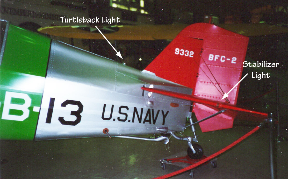
It's not clear what lights that the LSOs initially used at night for determination of pitch attitude. (Strictly speaking, "lining up the lights" would also only work if the airplane were on a descending approach, not the level approach then used, at least in daytime.) There are two candidates evident on carrier-based airplanes at that time, on the turtle back and on both sides of the horizontal stabilizer. This BFC-2 at the National Museum of Naval Aviation at Pensacola has both:
These are generally referred to as position or formation lights, which they may in fact have also been and simply adopted as a reference point for night carrier landings. (The turtle back light was also used at night to signal instructions before inter-plane communication by radio became standard.)

Some of the early monoplanes had what had come to be known as the approach light mounted just in front of the stabilizer, a more appropriate location given the use of the stabilizer as a reference in daytime conditions.

The aft-mounted approach light was subsequently augmented and then replaced before World War II with an approach-light unit mounted in the leading edge of the left wing* that placed red, yellow, and green-colored lenses in front of the light bulb. Depending on the angle it was viewed at, the light would appear to be red, yellow, or green to the LSO. Red meant too slow (nose up, tail down); green, too fast.Yellow was neither too slow or too fast.

This is the approach light installation in the XF4U-1:


The operation of the light was automatic. (A bypass switch was provided so the light would come on even when the tailhook was up and it could therefore be used by an LSO during field carrier landing practice.) Initially, the light came on when the tailhook was lowered. Before I looked at an F6F Hellcat wiring diagram provided by Larry Webster, I had thought that the exterior lights had to be on as well but apparently not on the F6F; it appears that the exterior lights had to be on for the F3D approach light to receive power.. Later, the operation of the light was enabled by the lowering of the landing gear: otherwise, the light remained off regardless of the position of the tailhook; when the landing gear was down, the light flashed if the tailhook was up and was on steady if the tailhook had been lowered. This provided a positive indication at night that both the landing gear and hook were down.

This is the light as installed in an F9F Cougar on display at the National Museum of Naval Aviation in Pensacola. Note that a high nose angle results in the light shining through the red lens from the LSO's view point. The box looks like it might be installed upside down because the angle markings that were used for adjustment to show an amber light at the correct approach angle aren't visible and there is no hole on the bottom of the box for the screwdriver used to adjust the angle of the box (see the F3D approach light illustration above.)


Here is the F2H maintenance manual illustration showing the relationship of the lenses and single light bulb and the means of adjusting the approach light, which was Government Furnished Equipment provided to the airplane's manufacturer for installation, to the proper angle for the airplane that it was installed in:
This gadget had a limitation with respect to providing the LSO with an accurate assessment of the aircraft's speed/angle of attack, since other factors like height, distance from the ramp, changing pitch, etc. would affect what color the LSO saw. According to the Boeing XF8B-1 pilot's manual, the LSO would see yellow when the airplane was 100 feet astern, 25 feet above the deck, and 10-12 knots above stall speed.

When the Navy added an angle-of-attack gauge in the cockpit of jets beginning in the mid-1950s, the three-lens approach light was replaced with a three-light system that provided the LSO with an indication of the approaching airplane's angle of attack regardless of its position relative to the desired glide slope and trend to or from that angle. It is still in use today—day and night—and consists of three separate lights mounted on the nose gear strut, in the leading edge of the left wing, or in the nose (E-2).

For some reason, the meaning of the lights was reversed: now red indicated fast (low angle of attack) and green, slow (high angle of attack), with yellow being "on speed," or strictly speaking, at the desired angle of attack. My guess is that the convention was reversed roughly when the angled deck, descending approach, and angle of attack indication for jets were introduced, i.e. the early to mid 1950s. My thinking is that red for slow was important for the level approach at minimum speed to axial-deck carriers because of the risk of stall. Angle of attack indication and a descending approach somewhat minimized that risk; fast may therefore have then been more of a concern due to arresting system and aircraft hook loads at the higher approach speeds of jets as well as the fact that being fast on a fixed glide slope meant a higher sink rate, something to be avoided as well.

Ed Barthelmes confirmed that the AD Skyraider three-lens approach light interpretation was reversed from the F3D convention, at least later on, and the same as the current one, i.e. red indicating fast.
The switch in convention undoubtedly applied to all carrier-based airplanes at the same time, at least in the same air group. It appears to have been of importance only to maintainers and LSOs and was therefore not communicated to those who had no need to know since I can find no mention of it in Naval Aviation News or other documentation.

The E-2 approach lights are mounted horizontally in the nose.
 However, it also has a blue position light on the lower left aft fuselage that LSOs can use to determine pitch attitude at night, reminiscent of the original approach light implementation.

For a little more on LSO history, see http://thanlont.blogspot.com/2009/05/waving-them-aboard.html

*An exception was the A4D-1 installation, which was on the right side of the nose landing gear strut. Presumably mounting it "externally"—rather than behind a hole in the wing covered by a plexiglass panel—was lighter (it also appears to be miniaturized) and it couldn't be on the left side of the strut because of the location of the shrink strut that compressed the nose gear as it was being retracted.(On later models, the three-light presentation was moved to the leading edge of the left wing.)
Ron Lewis reports that the red lens was on top from the first production A4D-1s, further evidence that the change was as early as 1954.