By Tommy H. Thomason

Sunday, December 20, 2009

It Seemed Like a Good Idea at the Time VII

By the beginning of World War II, the US Navy had transitioned from a silver fuselage/yellow wing paint scheme with complex and colorful carrier and squadron markings to a drab medium gray over light gray one with minimal markings. During the course of the war, the paint scheme became more complex, incorporating additional colors and counter shading but still with minimal markings from a squadron standpoint. However, by the time the war ended, its airplanes were generally painted overall sea blue with various marking schemes to denote the air group to which they were assigned.

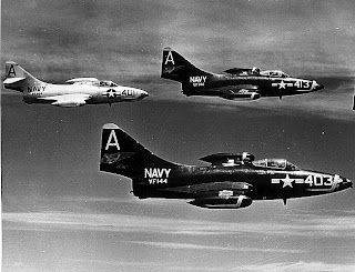
By 1950, the Navy had determined that overall dark sea blue was too visible under certain conditions for some missions, so it was inclined to adopt a paint scheme that was less so. One under consideration was the Air Force practice of leaving the aircraft unpainted, except for markings and skin panels that were not as corrosion-resistant as those formed from Alclad aluminum. Not painting aircraft had the additional benefit of reducing weight as well as initial and operating cost. Ever cautious, however, and in consideration of the much more corrosive environment that its carrier-based aircraft were subjected to, the Navy embarked on an evaluation program. Beginning in April 1952, the experiment was to involve approximately 100 F9F-5s (including F9F-5Ps and at least one F9F-2), all F7U-3s, 100 F2H-3s (and apparently some F2H-4s) and all FJ-2s. In cases where the external skins were not Alclad, they were painted with an aluminized lacquer that closely resembled the natural metal.

The natural metal F9F-5s and F2Hs were scattered among squadrons that also operated over-all blue airplanes.


The light gray areas on the F7U's aft canopy, lower side of the nose, and rudders are magnesium or other material which required painting for corrosion protection or to match the overall natural metal finish.

Some strangely colored F9F-5s resulted from aft fuselage substitutions to maximize the number of airplanes available for missions.


Although there are reports that a clear coating was used to protect the bare aluminum, it would appear from at least one report that the only protection suggested was a wax that was not readily available. By mid 1953, the results were already becoming apparent: corrosion ranging from slight to severe. Any cost benefit of not painting the aircraft was more than offset by the additional corrosion control effort required. One deployed squadron reported corrosion spots that varied up to 1/8" in diameter and several thousandths of an inch deep. In February 1955, the Navy decided to paint all its tactical airplanes in a gray/white scheme with the experimental airplanes to be painted by July 1955.

For more background on this experiment, see this 1953 issue of Naval Aviation News, pages 13-15.
Saturday, December 12, 2009

It Seemed Like a Good Idea at the Time VI

Boundary Layer Control increases the lift of the wing at low air speeds. Air drawn from the jet engine compressor is blown over the wing flaps, increasing the angle of attack at which the air flow separates from the upper surface of the flaps and the lift begins to decrease with increasing angle of attack rather than continuing to increase. In other words, postponing the wing stall to a lower speed/higher angle of attack than with unblown flaps.

This was of particular interest to the U.S. Navy because of the need to minimize the approach speed of carrier-based jet airplanes.  In 1951 a Navy engineer suggested using the problem as part of the solution, with the jet engine compressor being a convenient source of the air required.A test program resulted a few years later with a modified F9F Panther. At-sea carrier trials in 1954 demonstrated a significant reduction in approach speed, 10 to 15 knots depending on weight, which was limited by inadequate roll control at the lower speed rather than stall.

As a result, BLC was incorporated on a few US Navy airplanes in the late 1950s, although its first usage may have been in the Lockheed F-104 Starfighter which first flew in 1954. Like most gadgets, it was a mixed blessing. In at least two cases, the F4H Phantom and the F-8 Crusader (French and F-8J), it was an addition to an existing design to accommodate a necessary increase in gross weight. It might have been in the A3J Vigilante design from the beginning because the Navy wanted to be able to launch its long-range nuclear strike aircraft with no wind-over-deck at all. It also appears to have been in the F8U-3 from the beginning, Vought engineering having a penchant for incorporating this sort of thing, and the Blackburn Buccaneer. Note that all these were carrier-based airplanes, for which low-speed lift was far more important than land-based counterparts. However, as noted above, the F-104 incorporated BLC to compensate for its tiny wing and TSR2 did as well, because of its need for a high wing loading for high-speed low-level flight combined with a reasonable takeoff and landing distance.

This is a photo of the French F-8 flap system ducting taken and annotated by Tom Weinel:


Although it provided more lift at a given speed or the same lift at a lower speed as a non-blown wing, BLC was a maintenance burden, increased weight and complexity/cost, and robbed the engine of thrust on a wave off and takeoff. Troublesome failure modes included the fire hazard of a leak of the hot air in the ducting and a roll control problem on takeoff or landing if one side or the other failed to provide air for some reason. My guess is the overall experience in the 1960s resulted in BLC being infrequently taken out of the designer's tool box thereafter. The only current application that I can think of offhand is the Japanese ShinMaywa seaplane, which needs to take off and land at extremely low speeds in order to land in relatively high sea states in open water for at-sea rescue. In this case, the BLC air is taken from a compressor driven by a fifth and small turboshaft engine.

Thursday, December 10, 2009

The Reason for Those Lines on the Vertical Fin

I thought I'd mentioned this before in this blog but apparently I hadn't, because I can't find it. Back before the pilot and the Landing Signal Officer (LSO) were provided with indicator lights to insure that the airplane was at the correct angle of attack on approach, the left side of the vertical fin on most carrier-based airplanes* was marked with precisely positioned stripes. By noting which ones he could see with respect to a fixed point on the airplane, like the wing leading edge, the LSO could determine the airplane's angle of attack and signal the pilot to speed up or slow down if required.  These stripes were somewhat exaggerated on the mockup of the Douglas F4D Skyray and I'm not sure that the top one is properly located, but they illustrate the concept.

A closeup shows that the lines were marked in degrees.

The more subtle angle of attack markings used operationally are just evident on the leading edge of the fin of this F9F Panther.

These markings weren't of use at night, of course. In that case, the LSO relied on an "approach light" in the leading edge of the left wing. There were three colored lenses in front of the light so that he saw green for too slow, red for fast, and amber for on-speed based on the attitude of the aircraft at the proper approach altitude. The light only came on when the hook was lowered so it provided a positive indication that the hook was down at night. (A field carrier-landing switch was provided for practice night approaches ashore.) LSOs also used the relative orientation of the running lights (and on propeller-driven airplanes, the flames from the exhaust stacks) to determine the speed (actually angle of attack) of the approaching airplane.

Within a few years after angle-of-attack measurement and cockpit display were added to Navy carrier-based jets in the early 1950s, the LSO was provided with an angle-of-attack indication via three lights. Again slow (actually, too high an angle of attack) was green, on-speed was yellow, and too fast was red. The lights were generally located in a box mounted on the nose landing gear as shown here.

*I don't know why, but F2H-2 Banshees didn't have these stripes even before angle of attack indication became available. On the FJ-1 and F2H-1, they were placed on the nose - on both sides of the FJ-1, probably because North American didn't know what they were for...